
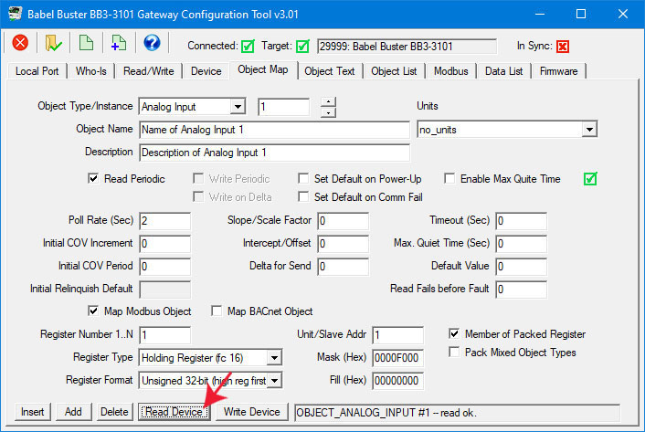
You gave the BB3-3101 gateway its identity as a BACnet device on the Device page in the previous section. The Object Map page is where you tell the gateway what to do.
The properties that define each BACnet object in the gateway are displayed on the upper section of the Object Map page.

| Object Type/Inst | Select BACnet object type from the list, and enter or scroll to the desired object instance. The object number will stop scrolling at the limit set by object counts on the Device page. |
| Object Name | Enter an alphanumeric name for the object. The name must be unique, and will be checked for uniqueness. If it is a duplicate name, you will see an error message and the dialog will remain open. |
| Description | Enter any arbitrary description for this object. |
| Units | Select a BACnet units type from the list. |
| Read Periodic | Check this box if the BACnet object will be periodically reading from the slave Modbus device or slave BACnet device. ‘Read’ is valid for Input and Value type objects. |
| Write Periodic | Check this box if the BACnet object will be periodically writing to the slave Modbus device or slave BACnet device. ‘Write’ is valid for Output and Value type objects. |
| Write on Delta | Check this box if the BACnet object will be writing to the slave device only when the object’s value changes by a specified ‘Delta’. It is valid to check both Write Periodic and Write on Delta at the same time, or check just one or the other. ‘Write’ is valid for Output and Value type objects. |
| Set Default on Power-Up | Check this box if the object should assume the default value every time the BB3-3101 powers up. |
| Set Default on Comm Fail | Check this box if the object should assume the default value when communication with the slave device has failed some number of times. |
| Enable Max Quiet Time | Check this box to enable maximum quiet time. This is applicable to an object which is set to Write on Delta. The result is that if there has been no change within the max quite time, the slave device will be re-written anyway. |
| Poll Rate (Sec) | This rate applies to periodic reading or writing, and simply specifies how often the slave device is read from or written to. |
| Initial COV Increment | The initial COV increment specified here will apply when another BACnet client subscribes to this object’s COV with a simple Subscribe COV. This initial increment will remain in effect until some other BACnet client writes a new COV increment to this object. If the BACnet client does a Subscribe COV Property, then the COV increment specified in the subscription is used instead of this Initial COV Increment. COV Increment applies only to Analog objects. COV will be reported on any change in a Binary or Multi-state object. |
| Initial COV Period | The initial COV Period will take effect when the Babel Buster is first powered up. After that, any BACnet client can write a new COV Period to the object. The COV Period produces a periodic COV notification regardless of value change. COV Period is valid for all object types. Enter zero to disable periodic COV and provide notification only upon change specified by the increment. |
| Initial Relinquish Default | The initial Relinquish Default will take effect when the gateway is first powered up. After that, any BACnet client can write a new Relinquish Default value to the object. The Relinquish Default value applies to any Commandable object, and the Present Value of the object will assume this value when all 16 priorities have been relinquished. |
| Slope/Scale Factor | Scaling applies the formula y=mx+b. When reading from the slave, the raw data as read is multiplied by the scale factor, then the offset is added to produce the resulting Present Value. When writing to the slave, the offset is first subtracted from Present Value, and that result is divided by the scale factor to produce the raw data actually written to the slave device. NOTE: If no scale factor is given (zero is entered), no scaling will be done, as if slope=1 and intercept=0. |
| Intercept/Offset | The offset portion of the scaling as noted above. |
| Delta for Send | Enter the threshold for writing when configured to Write on Delta. If a value of 5.0 is entered, the value must change by more than 5.0 before the slave device will be written to. Delta applies only to Analog objects. Binary and Multi-state objects will send on any change when Write on Delta is enabled. |
| Timeout (Sec) | Timeout for Modbus queries is specified on the Modbus page. When the remote device is another BACnet device, the timeout given here specifies the amount of time the BB3-3101 will wait for a response before calling it an error. |
| Max. Quiet Time | This is applicable to an object which is set to Write on Delta. The result is that if there has been no change within this amount of time, the slave device will be re-written anyway. In addition to entering a nonzero value here, you must check the ‘Enable Max Quiet Time’ box. |
| Default Value | This is the value that should become the Present Value upon power-up or upon communications failure, if either of these options are selected by the appropriate check boxes above. |
| Read Fails before Fault | When ‘Set Default on Comm Fail’ is checked, this entry will allow you to disregard a small number of spurious errors. At least this many errors must occur consecutively before a fault will actually be flagged. Causing a fault as a result of a single instance of spurious noise on a communication line can be a nuisance. This setting allows quieting the nuisance fault notifications. |
You map the BACnet object to a Modbus register, assuming the gateway will be operating as a Modbus master, by clicking on "Map Modbus Object". When you do so, additional parameters specific to mapping of a Modbus register will appear.

| Map Modbus Object | Check this box to map the displayed BACnet object to a register in a slave Modbus device. (If using the BB3-3101 as a Modbus slave, do not check this box, and refer instead to Appendix D for slave register mapping.) |
| Register Number 1..N | Enter the Modbus register number between 1 and 65535. The register number is raw address plus one. Therefore if your Modbus device’s documentation indicates that the first register is at address zero, add one to every address to get the register ‘number’. Note: Do not enter Modicon numbers like 40001 for the first holding register. If the Modbus device documentation indicates register 40001, this means you should select "holding register" as the register type, and just "1" for register number. |
| Register Type | Valid register types are Coil, Discrete Input, Input Register, and Holding Register. Coil and holding register have two options, each indicated by a different "fc" number in parenthesis. This number is the function code for writing to these registers. FC 5 and 6 will write only a single register, while FC 15 and 16 will write multiple registers. Codes 15 and 16 will also be used by default to send a single register. Some Modbus slaves are particular about which function code is used to write, and you need to make the appropriate selection here. |
| Register Format | Register format options include 16-bit, 32-bit, or 64-bit unsigned or signed integer, or floating point. When 32-bit integer or floating point are selected, you are really reading or writing two consecutive registers. For 64-bit, you are reading/writing four consecutive registsers. Modbus protocol defines a holding register (or input register) as strictly 16 bits. Any larger data element is spread across multiple registers. When using register pairs, the order in which the registers are interpreted is not standardized. You have the option of selecting either order by from the list of formats.
There is also a Bit format. This ONLY applies to coil and discrete input. If you are attempting to read a single bit from a holding register, you must read the register as unsigned 16-bit (or 32-bit if applicable) and then apply a mask. The format 'Bit' refers to the format of data in the Modbus slave; it does not refer to your desired end result. |
| Unit/Slave Addr | This is the Modbus RTU slave device address that the gateway will query when the gateway is Modbus master. If the TCP version of gateway is used, the unit is used to look up the IP address of the slave. This value is not used when the gateway itself is the slave. |
| Mask (Hex) | When extracting a single bit or set of bits from a packed Modbus register, this mask specifies where in the register the desired bits are found. This mask is entered as a 4-digit hexadecimal number representing 16 bits. After masking data read from Modbus by performing a bit-wise And between the data and this mask, the resulting data is right shifted so that the least significant bit of interest becomes the LSB of data. When writing, this process is reversed.
NOTE: The mask is only applied if "Member of Packed Register" is selected. |
| Fill (Hex) | Applicable only when writing, this value is optionally used to always set specified bits. This value is entered as a 4-digit hexadecimal number representing 16 bits. The data to be written to the Modbus slave is bit-wise logical Or-ed with this value just before being written to the device.
NOTE: The fill is only applied if "Member of Packed Register" is selected, and is only applicable when writing to Modbus. |
| Member of Packed Register | Check this box if the BB3-3101 should apply mask and fill, and should look at the next consecutive object map, or is included in the group started by a previous object map, to potentially combine this and at least one other object map to collect multiple BACnet objects into a single Modbus register for writing, or distribute from a single Modbus register to multiple BACnet objects when reading. |
| Pack Mixed Object Types | Check this box if your packed Modbus register needs to be mapped to more than one type of object, e.g. both Binary and Analog objects are involved. Do not check this box unless truly needed because it does result in searching all object maps, looking for members of the group, every time this object is processed. Unchecking this box and making sure object maps are in consecutive order when only one object type is needed will result in more efficient processing. |
The options available for Modbus register format are displayed in the drop-down list. The corresponding notation that should be used when creating a CSV file is shown in the table below. If no format column is included in your CSV file, unsigned 16-bit register will be assumed.

Format designations as used in CSV or XML files:
| CSV Notation |
Description |
| SIGN | Signed 16-bit |
| UNSI | Unsigned 16-bit |
| SDBE | Signed 32-bit (high reg first) |
| UDBE | Unsigned 32-bit (high reg first) |
| FPBE | Floating Point (high reg first) |
| BBIT | Bit (coil/discrete) |
| SDLE | Signed 32-bit (low reg first) |
| UDLE | Unsigned 32-bit (low reg first) |
| FPLE | Floating Point (low reg first) |
| SQBE | Signed 64-bit (high reg first) |
| SQLE | Signed 64-bit (low reg first) |
You can map the BACnet object in the gateway to read or write a BACnet object in some other BACnet device on the same network. This is most often used if the gateway will be treated as a Modbus slave, and some other Modbus master wants to read and write data in a BACnet device on your MS/TP network. When you click "Map BACnet Object, the parameters specific to mapping this object to another BACnet device will appear.

| Map BACnet Object | Check this box when the BB3-3101 should look for another BACnet device as the slave device (instead of a Modbus slave). This box can be checked any time, but is of particular interest when using the BB3-3101 as a Modbus slave and BACnet master for connecting BACnet devices to a Modbus network. |
| Remote Device Instance | Enter the device instance of the remote BACnet server (slave). The remote device must be able to support Who-Is/I-Am for locating device by device instance. |
| Object Type | Select the object type from the list, such as Analog Input, etc. |
| Mac address (if no who-is) | Sets the MS/TP MAC address (station ID) of the remote device if it is a slave-only device or does not support dynamic binding (Who-Is/I-Am). Normally you would leave this set to zero so that the remote device will be discovered automatically when the gateway broadcasts a "Who-Is" message. This setting applies to MS/TP only. BACnet IP devices (on the other side of a router) are required to support dynamic binding (Who-Is/I-Am). |
| Property | Select the property to be read/written. A collection of most often used property types are included in the drop list. If the desired property is not shown, select ‘Other-->’ and enter the property type code in the window next to the list. The property type codes are those defined by the BACnet standard. For example, Present Value can also be obtained using ‘Other --> 85’. |
| Instance | Select the object instance. There are usually multiple instances of objects in a device. This identifies which one you want. |
| Array Index | Some properties are an array of values. If applicable, enter the array index here. Enter -1 to indicate no array index is to be used. Zero is a valid index. |
| Bit Num | When the property type is a bit string, this entry may be used to specify which bit you wish to single out, especially when applying the result to a Binary object. If no bit number is provided, the entire bit string will be assembled as an integer value representing a mask containing all bits. |
| Data Type | Select the data type expected from this list. Note that some types are not supported here. Character string, for example, is one type of data that cannot be forced into Analog, Binary, or Multi-state objects by the BB3-3101. |
| Priority | You must use a priority level when writing to a Commandable object. If the object is not commandable, you must select ‘None’ here to avoid having the request rejected. |
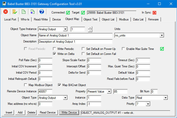
Be sure to set the Priority when writing to a Commandable object. Failure to do so will result in the request being rejected. Conversely, be sure to select "None" when writing to a non-commandable object. Including priority for an object that does not expect it will also result in the request being rejected.
NOTE: There is specific behavior that applies when a commandable object (e.g. Analog Output) is writing to another commandable object as illustrated above. In this instance, priority 7 will be used to set the Present Value of the remote object as long as the local object is not in the relinquished state. If no priorities are set in the local object, then NULL will be written to priority 7 in the remote object effectively relinquishing that priority in the remote object.
Clicking ‘Insert’ will insert a new map before the currently displayed object map. Clicking ‘Add’ will insert a new map after the currently displayed object map. Clicking ‘Delete’ will remove the currently displayed map and slide the remainder of the list up by one slot on the list.
The only time position matters much in the list is when configuring a packed register that maps a single Modbus register to multiple BACnet objects. The members of the packed register must appear in consecutive maps unless the ‘Pack Mixed Object Types’ is checked. Do not check ‘mixed object types’ unless you really need to mix analog and binary objects (for example) in the same packed Modbus register. Packing mixed object types is very inefficient since the gateway must scan the entire list of object maps for every instance of packed register. When packing the same object types, placing them in consecutive maps results in very efficient execution.
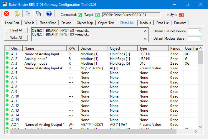
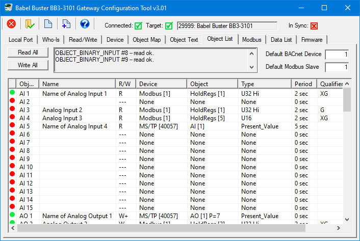
Our currently defined object list is as illustrated above on the Object List page. Go to the Object Map page, select the insert point (object number) and click Insert.
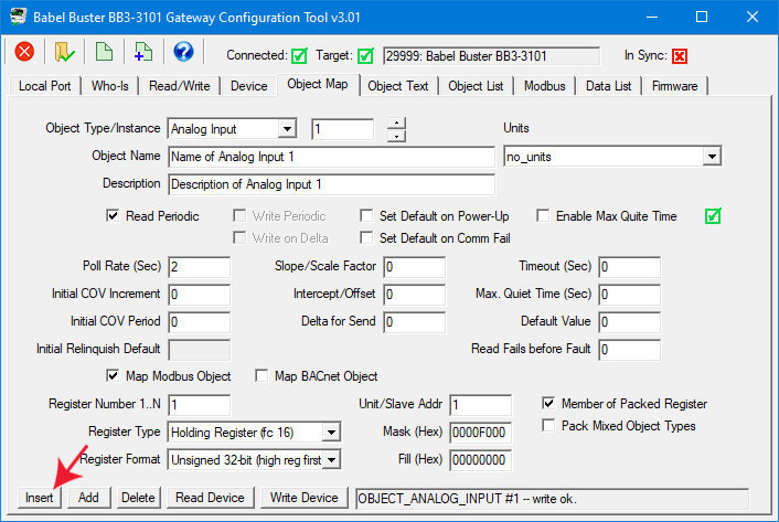
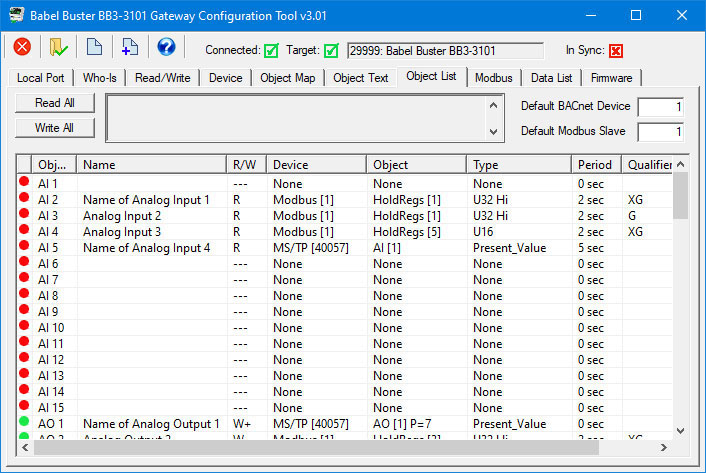
After clicking Insert, the new map appears before the indicated object number, and existing object maps are moved down the list.
Clicking Delete will remote the current object and move maps up the list.

Clicking Add will insert the new object after the current object, and move the remaining object mappings down by one.
When changes are made, the in-sync icon changes to a red X on the right hand side of this page. When properties are either read or written, the device is now in sync, and the red X changes to a green check mark. This icon will change on an object by object basis indicating those objects that are in sync.
When all aspects of device configuration are in sync, between device and tool, the ‘In Sync’ icon in the top right corner of the screen will change to a green check box. This is the master In-Sync icon, and will be green only when all other in-sync icons are also green. This icon is effectively a summary icon.
The device properties and object maps are stored in the same XML file. Refer to section 7.6 of this user guide to review file import and export features. They work the same whether accessed from the Device page or Object Map page. The file type exported or imported from either of these pages is an XML file. Note that the file type is not the same on the Object List page, where it expects a CSV file instead.

Note: If you have an XML configuration file saved from a BB2-3010, you can directly import that into your BB3-3101 by simply opening that file on this page.
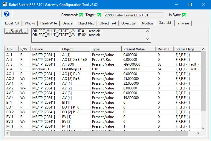
One way of detecting a communication failure is to look at the reliability code in the gateway's local object. A reliability code of zero means everything is OK. A non-zero reliability code means there is a problem. For example, if the gateway's object is polling a remote Modbus device, then a reliability code of 64 means timeout, and that in turn most often means no connection. If the local object is mapped for polling an remote BACnet device, then a reliability code of 82 means timeout. Several other reliability codes are possible and these are listed in section 12.2.
The reliability code can be read as a property by another BACnet client. The reliability codes can be read as Modbus register values if the gateway is functioning as a Modbus slave.
There is another alternative for flagging data as invalid due to a communication error. You can configure a default value which the local object should assume if it fails to retrieve a value from the remote device. This only applies to local BACnet objects that are configured to read data from a remote device. Trying to write a default value upon communication failure doesn't make any sense since inability to access the remote device was the problem in the first place.
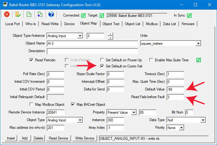
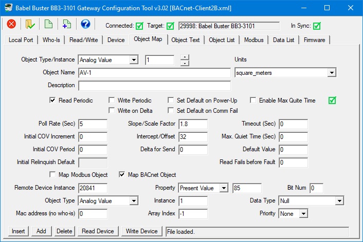
There are three values you need to configure to implement the default on fail. The configuration for an object mapped to read from a remote BACnet device is illustrated here.
The configuration for an object mapped to read from a remote Modbus device is illustrated here.
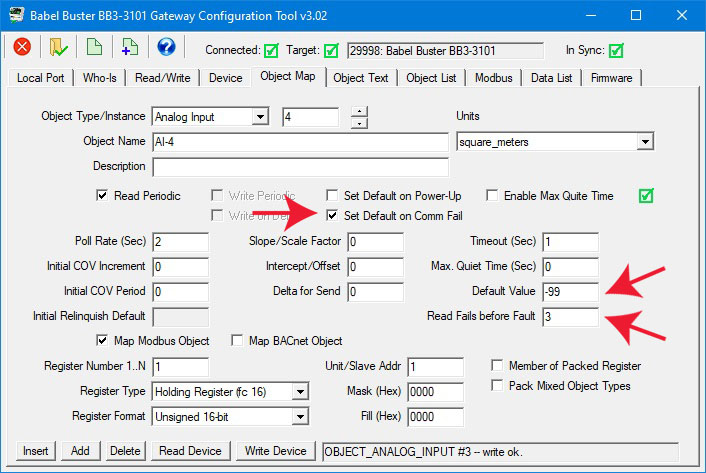
The "Read Fails" count of greater than one prevents spurious communication problems from triggering the default value. The problem must persist before the default value will be applied.
The Data List page with these two objects in fail mode is illustrated here.
The scale and offset, or slope and intercept, settings allow data conversion "on the fly". As noted earlier, scaling applies the formula y=mx+b. When reading from the slave, the raw data as read is multiplied by the scale factor, then the offset is added to produce the resulting Present Value. When writing to the slave, the offset is first subtracted from Present Value, and that result is divided by the scale factor to produce the raw data actually written to the slave device. NOTE: If no scale factor is given (zero is entered), no scaling will be done, as if slope=1 and intercept=0.
One of the more commonly used conversions is degrees Celsius (C) to Fahrenheit (F). The formula is
F = 1.8 * C + 32
Reading degrees C from remote device and converting on the fly to degrees F in the gateway's local object would be configured as illustrated below. The data read from the remote device is multiplied by 1.8, then the offset of 32 is added.
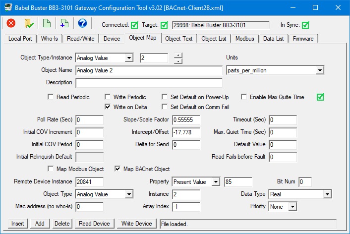
Writing degrees F from gateway's local object to degrees C in the remote device is configured the same way as illustrated below. When writing, the math is reversed, so in this case, the offset of 32 is first subtracted, then the value is divided by 1.8.

Writing degrees C from gateway's local object to degrees F in remote device is illustrated below:
If the numbers in this last example don't seem to make sense, revisit the previous example, and get out your calculator and try it out.