You need to do these three things in general to configure the gateway:
(a) Configure the gateway as a BACnet device.
(b) Configure some object mappings.
(c) Configure the Modbus port.
There are a few options for getting the objects and object mappings defined, and these are discussed in the following parts of this section of the user guide. Configuring the gateway as a BACnet device and setting up the Modbus port are discussed in sections later in this user guide. Later sections will also go into more detail about the features of each of the object mapping pages talked about here. The majority of your time spent configuring the gateway will be spent on the object mappings, so we want to start by taking a look at that process, and the options you have for approaching that task.
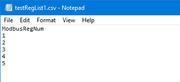
This configuration tool attempts to simplify configuration by recognizing the most minimal CSV file. If you only need to read a list of Modbus holding registers, then the CSV file can be as simple as a list of register numbers, with the heading "ModbusRegNum" as illustrated below. Note that these are proper register numbers, not Modicon style numbers. If your documentation shows register numbers starting at 40001, then either use the Modicon form of CSV illustrated in the next section, or drop the 40000 part and just enter 1 where the documentation shows 40001. If your Modbus documentation shows holding register numbers starting at 0, then add 1 to every register number when creating the CSV file.

If you are using a spread sheet program to enter the numbers, then be sure to "save as CSV" when saving the file. You can also use a simple text editor such as Notepad to enter the CSV as plain text, as illustrated below. Be sure to save your text as a .csv file, not .txt. The configuration tool needs to see a file name ending in .csv.
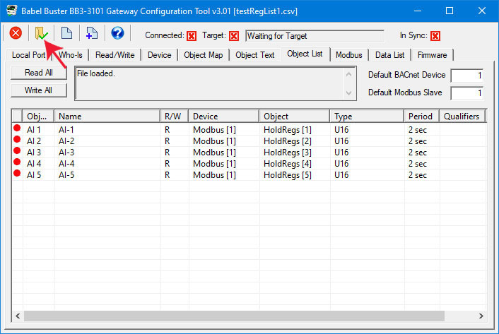
Once you have your file ready to go, open the configuration tool, go to the "Object List" page, and click the file open icon. Then find your *.csv file and open it. Given only a list of register numbers, they will default to reading as unsigned 16-bit holding registsers, and the values will be assigned to BACnet Analog Input objects. All of the objects will be configured to read the Modbus registers. If you need to write some of the registers, continue on to the next example.
When you load configuration from a file, object counts on the Device page are automatically allocated, provided no objects had been previously allocated. If you load a file, then add some lines to the file, and try to load the new file, you will get an error message saying something about "object out of range". This means the configuration tool retained your previous object counts, but you now need more. To remedy this problem, go to the Device page, and click the "new" icon (that would be the left-most icon in the top toolbar). Clicking the "new" icon clears everything so you can start over with a new number of objects.
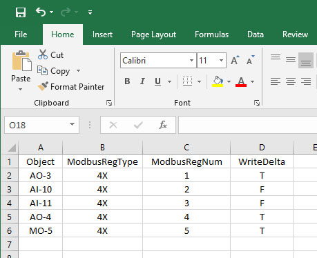
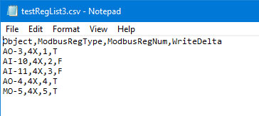
The above example shows reading a set of Modbus holding registers. Suppose you want to write some of them, and you only want the Modbus register to be written to (or updated) when a new value is written to the corresponding BACnet object. To accomplish this, add a second column labeled "WriteDelta" (no spaces between words). Enter T if you want to write the Modbus register, or F to read it instead.
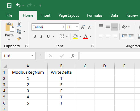
The plain text version of this example looks like this:

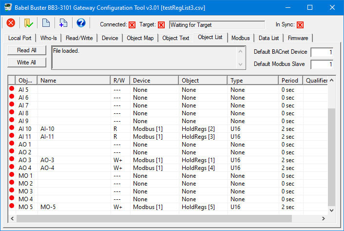
Upon loading this version of CSV file, note that the registers flagged for writing are assigned to Analog Output objects rather than inputs. The Analog Output object is what BACnet expects to write to in the gateway. When the respective Analog Output object is written from BACnet, the gateway will write the new value to its assigned Modbus holding register.
Also note the number in brackets after "Modbus" in the Device column. This is the Modbus RTU slave address. The value shown in the "Default Modbus Slave" window will be used when loading the CSV file when that column is not explicitly provided in the CSV file.
To see a complete listing of all possible CSV columns, refer to Appendix A.

The next example is simply for additional illustration purposes. By default, loading the CSV file will start with object 1 and count up sequentially in assigning objects. If you have some reason to pick specific objects, or want to use objects other than the default Analog type, you can explicitly select BACnet objects to be assigned as illustrated here. In addition, if you want to specify Modbus registers other than holding registers, you can do that with the ModbusRegType column. This example still results in all holding registers because they all indicate "4X", but if you wanted to change some of the registers to read input registers instead, then you would replace "4X" with "3X".
The plain text version of this CSV file would look like this:
After loading this CSV file, the Object List page would look like this, assuming you scroll down a bit. With Analog Input objects explicitly starting at 10 in this example, the first 9 objects will be present but unused at this point.
Older Modbus documentation, and some newer documentation using older conventions, will refer to the device's first holding register as number 40001. This is short hand for saying "holding register 1". To get beyond the limit of 9,999 registers using this numbering scheme, some documentation will use 400001 instead for the first holding register. This style of Modbus register documentation is a convention first introduced by Modicon back in the 1970's when Modbus was first created. The current Modbus protocol specification does not recognize Modicon notation. Actually, it does not recognize register "numbering" either, it recognizes raw addresses where the first holding register is 0000.
Some Modbus documentation will use 40001 to represent the first holding register. Some will document 0 as the first register. A majority of documentation will reference the first holding register as 1. You need to spend some time studying the documentation to try to determine which convention has been used. If you see a lot of numbers in the 40,000 range, it is Modicon. But otherwise, you have to look for evidence as to whether register numbers (or addresses) start at 0 or 1. If they start at 0, add 1 to all numbers when entering configuration parameters in the Babel Buster configuration tool.
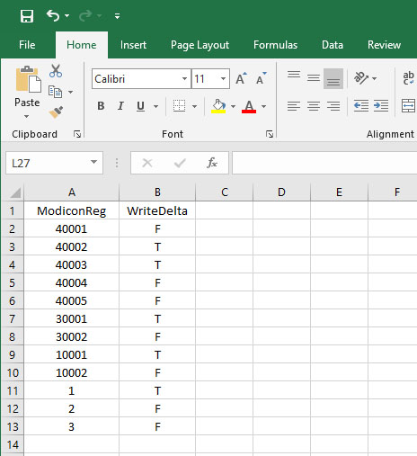
The following spread sheet shows holding registers 1 through 5, and input registers 1 and 2, expressed in Modicon notation.

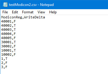
This would be the raw text form of the CSV file:
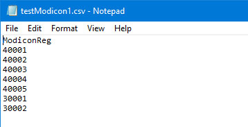
Upon loading this CSV file, the Modicon shorthand numbers are converted to register type and register number as illustrated here.
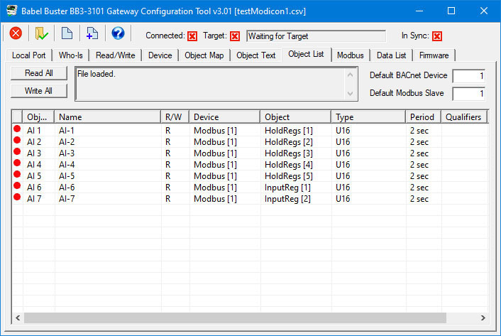
The same options for additional columns in the CSV file noted above are available for Modicon register notation. In the following example, we add some discrete inputs and coils, and mix up the reading and writing a bit.
The plain text version of this CSV file would look like this:
After loading this CSV file into the configuration tool, the BACnet object assignments and Modbus mappings look like this:

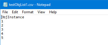
The majority of applications for a BB3-3101 gateway are for putting a Modbus device on a BACnet network. But suppose you have a Modbus PLC, running as a Modbus master, that wants to read data from one or more BACnet devices. These gateways are equally capable of going this direction, and the configuration tool provides CSV import flexibility to simplify that type of configuration as well. In its simplest form, you need only list object numbers, provided they are all Analog Input type BACnet objects.

The plain text would look like the following. Be sure to save your text as a .csv file, not .txt. The configuration tool needs to see a file name ending in .csv.
After loading this CSV file into the configuration tool, the Object List screen looks a bit different compared to the Modbus examples above. The Device column now shows "MS/TP" instead of "Modbus" because this is now what the gateway is going to be polling instead. The number in brackets after "MS/TP" is the device instance, and will default to whatever is entered in the Default BACnet Device window. The objects that will be read from that other MS/TP device will be the object numbers listed in the CSV file, and will by default be assigned as Analog Input types both in that device and in the gateway. By adding additional columns to the CSV file, you can specify different object types. Of course, you can also go to the Object Map and make changes after loading the CSV file.
Although a bit more complicated to set up as a CSV file, you can have the same gateway polling BACnet devices on one side, and polling Modbus devices (with gateway configured as Modbus master) on the other side. This means the gateway would actively read data from BACnet devices and write it to Modbus devices, and/or vice versa.
And just in case you were wondering, no, you cannot load multiple CSV files on top of each other. You need to combine them into one consistent CSV file first, and then load. By consistent, we mean the file must have one and only one header line, and it must be the first line in the file. Each following line must have as many entries on the line as the header line had.

When only a list of object numbers are provided in the CSV file, they will default to being all Analog Input objects. To specify different types of objects in the target MS/TP device to be read (and/or written), you would add the ObjType column.
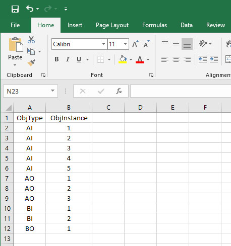
The plain text looks like this:

When this CSV file is loaded into the configuration tool, the resulting object map looks like the following. Note that the objects allocated inside the gateway are selected by the configuration tool to correspond as appropriately as possible to the objects in the target device. If you want to explicitly assign objects in the gateway rather than let the tool select defaults, then add the Object column in which you specify objects such as "AO-3" and "AI-10" as seen in a previous example.

When you built a configuration starting with a CSV file, object counts were calculated for you as the file was loaded. When you start from scratch and build a configuration manually, you need to start by deciding how many objects to allocate and what types of objects you will need. The gateway has a finite amount of memory available for buffering data for the BACnet objects. To provide maximum flexibility, that available memory is not divided up among a fixed set of objects. That resource pool can be reallocated any way you like, up to a total of 1024 objects.
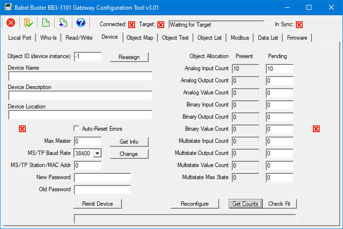
Assuming the configuration tool is offline, not connected to any gateway device, you can allocate objects by entering numbers in the second column to the right of the list of object types on the Device page. Then click the 'Get Counts' button to accept those numbers as your configured set of objects.
If you the configuration tool is online, connected to a gateway via the MS/TP network, then clicking the 'Get Counts' button will query the gateway to ask it how many objects it currently has in its resource pool. If you need to change the number of objects in the gateway device, the procedure for doing that is outlined in section 7 of this user guide.
In the example illustrated below, we have allocated 10 Analog Input objects.
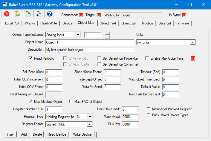
Once you have allocated some objects (or retrieved object counts from a connected online gateway device), you may proceed to the Object Map page where you can enter all of the parameters for mapping that BACnet object in the gateway. Regardless of what the object is going to be used for, you need to provide some basic information to allow that object to really behave as a BACnet object. One of the requirements is that each object in a BACnet device is required to have a unique object name. Description is optional; however, some BACnet clients will expect to see a description in addition to object name.
After defining the minimum requirements for existing as an object, you then have the option of deciding what that object is going to do for you in the gateway. For the gateways in question in this user guide, the most common application is going to be reading or writing a register in a Modbus device. To map this object to a Modbus register, click on 'Map Modbus Object'. When you do that, additional windows will appear which allow you to select register number, register type, data format, slave address or TCP device number, and so on.
Once you have entered object information and mapping information, this new object will now appear on the list on the 'Object List' page in the same manner as if you had imported a CSV file to configure the gateway.

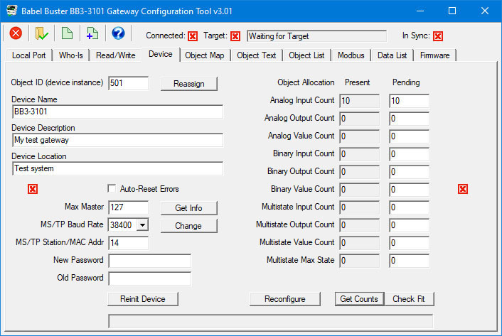
In order to have a completely functioning BACnet device on the MS/TP network, you do need to define a few additional parameters on the Device page. From the BACnet perspective, these are properties found in the BACnet Device object for the gateway. As with all other objects in the gateway, the Device object needs to have a unique device name. Description and location are optional. You also need to assign an Object ID or device instance to the Device object. This number needs to be unique on your BACnet network, and this is the number that will be returned by the gateway in response to any Who-Is request on the network.
You must enter port parameters for the MS/TP port. Max Master will default to 127, and you should leave that number alone unless you understand what this number does and you understand your reasons for changing it. Set the baud rate to match the baud rate of your network. Set the MAC address to a number that is not already used on the network. Note that incorrect baud rate, incorrect max master, duplicate MAC address, or duplicate object instance will all cause communication problems, not only for the gateway but for other devices on the network.
One of the most common problems in the case of a gateway not functioning as desired is entering configuration changes into the configuration tool software but forgetting to actually transmit that information to the gateway device. The preceding discussions about building configurations talked about the available methods for creating a configuration. You do need to refer to later sections in this user guide to review the full details of everything configured on each of the pages in the configuration tool, and in particular, how you send that information from the tool software to the actual physical device. We are getting a little ahead of ourselves by talking about how to verify configuration in the device at this point in the user guide, but it is a topic general in nature, so it is provided here for future reference.
If you think the gateway is configured, but it is not functioning as desired, read the configuration from the device to be sure what is actually in the device is the configuration you thought was in the device. You will notice throughout the configuration tool pages that there are a number red 'X' boxes or green check boxes (red and green dots on the list pages have the same meaning). Pay attention to these. If any boxes are the red X, it means what you see on the screen may not be in sync with what is in the device. You have two options to get the red X to become a green check mark: Either read from the device or write to the device. If you read from the device, the tool will display whatever it found in the device (potentially replacing any changes you had made on the screen). If you write to the device, you will replace the configuration previously in the device with whatever is displayed on the screen.
Until all of the red icons are replaced with green icons in the configuration tool, you have no assurance that the configuration in the device actually is what you think it is. If you are having problems with a gateway not doing what you want, make sure you are looking at all green icons first, then review the configuration to verify that the mappings are asking for the registers you intended, and so on.
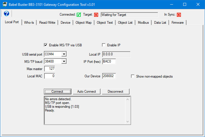
Start by connecting the tool to the network using the Local Port page illustrated below. Refer to section 4 for full detail on what all you need to do on this page and what your options are for connecting to the physical network.
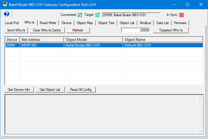
The configuration tool will transmit the BACnet "Who-Is" message on the network when you click "Send Who-Is". The list will begin to populate, and may be a long busy list on a large network. After you click the Refresh button a time or two, the tool will show a list of all BACnet devices found on the network. Select your gateway from this list. Refer to section 5 in this user guide for more about the Who-Is page.

If you are on a busy network, you can enter the device instance nexted to the "Targed Who Is" button, then click that button. Once the device instance is found, you may click Refresh to also retrive the model and name.
If you have not previously set the device instance in a brand new BB3-3101, its device instance will be 20800. Use that default instance instead of the 29999 shown in this example.
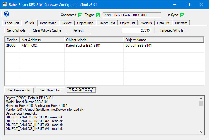
You can go to each of 5 different pages in the tool and click the 'Read Device' button on each page to get the information from the device that will appear on that page. The short cut method is to simply click the "Read All Config" button on the Who-Is page. While reading all of the configuration information from the connected gateway, progress will continue to update in the log window at the bottom of the Who-Is page. Wait for this activity to stop, and then proceed to review the information on other pages in the tool.
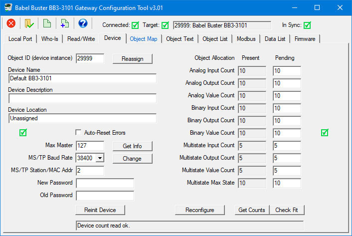
Following the "read all" process, the Device page will now show the BACnet Device object properties as well the counts of different types of objects currently found in the gateway.
The Object List page will show the list of objects in the device and display mapping information. You can also go to the Object Map page and review (and optionally change) the details of the object mapping.

This topic is provided here for future reference. Until you have configured the gateway for the first time, you can disregard this procedure. But at some point, you may find that you need to add some objects to a gateway that had been previously configured. The details for establishing the initial configuration are talked about both above and in the next several sections of this user guide. However, the process for modifying the object counts in a device that has already been configured requires going back and forth between more than one page.
It is important to note that any time you change the object count allocation in the physical gateway device, you will erase whatever configuration had been in the previously allocated objects. You are effectively wiping the slate clean. While starting from a clean slate can be advantageous at times, you may not want to wipe the slate clean, just change counts. The procedure for effectively doing this is to save your objects, wipe the slate clean, then put the previousl objects back in place but within the newly allocated set of objects.
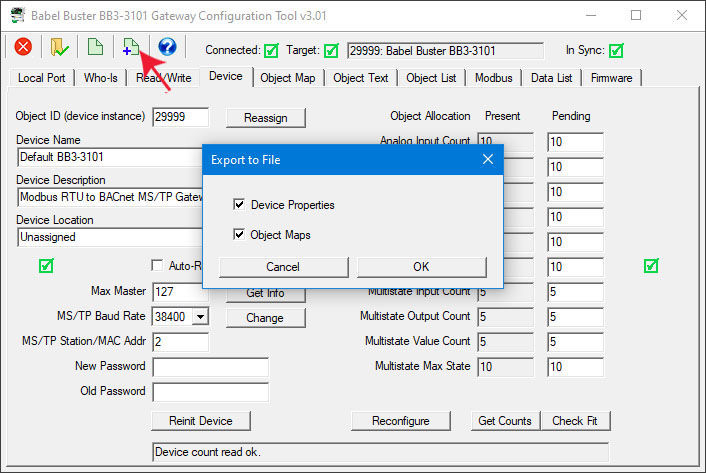
Start by connecting to the device and reading all configuration from the device as outlined in the above discussion (3.5) on verifying your configuration. After that process is complete, go to the Device page and click the new file icon. You have the option of exporting device properties, object maps, or both. Although you will only be needing the object maps for this procedure, it is a good idea to save everything in the event you want to completely replicate the gateway device. Click OK to save the file.
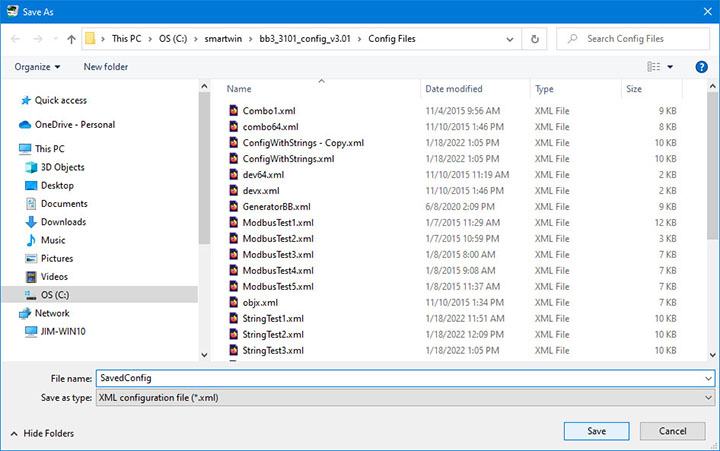
The familiar file dialog will appear. Find a directory where you want to put your file, and enter a file name for the configuration XML file about to be created.
Once you have saved the configuration, go to the Device page and enter the new counts in the column to the right of the list of available object types. The box that you are allowed to edit is the pending or proposed new count. The grayed out box is the counts as they actually exist prior to any changes.
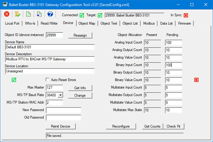
You are limited to a maximum of 1,024 total objects, but you may allocate them any way you wish. If you attempt to allocate more than the maximum number of objects as depicted in the screen shot below, then the counds will be forced within bounds.

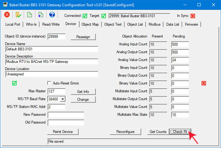
It is recommended that you click the "Check Fit" button to be sure the object counts you have requested are within bounds. The example above is not. When you click Check Fit, counts will be limited and the example illustrated above will lead to the result illustrated below.
After entering the new counts and verifying them by clicking Check Fit, click the Reconfigure button.
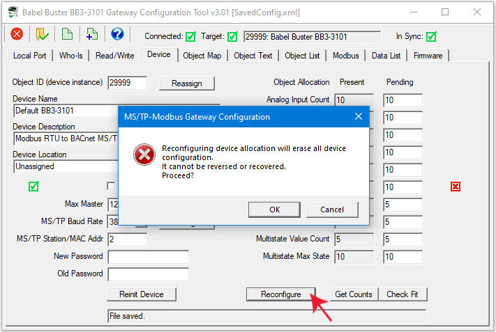
A dialog appears reminding you of what you just read above about wiping the slate clean. If you click OK, then the new counts are sent to the gateway device.
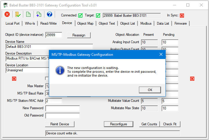
You have one last opportunity to abandon your changes. The new counts are in the device but waiting for the final authorization to act on them. If you skip the next step of clicking the Reinit Device button, and power cycle the device instead, nothing will have changed in the device (and reconnecting and clicking Get Counts will retrieve the old counts and all configuration is still intact).
You must enter the reinitialize password in the Old Password window before the reinitialization will be accepted. This defaults to "buster" when initially shipped from the factory. Enter the password and then click the Reinit Device button.

If you are watching the device itself just after clicking Reinit Device, you will see lights inside change and become red for a short time. After the red lights go out, you may now continue. If you do not have the device in sight, just wait for 30 seconds or so, and attempt the Get Counts noted next. If you get a timeout message, wait a bit longer and try again.
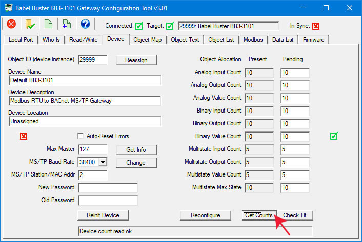
Following the reinitialization (which results in a BACnet warmstart execution), click get Counts to verify the updated object counts in the device. Although you probably didn't change any other Device object parameters, click the Get Info page anyway just to get the entire Device page in sync (all icons green).

The configuration tool knows you just wiped the slate clean in the device, so it wipes its own slate clean as well. There will be no object mapping information displayed, only blank objects (with the number of objects corresponding to the object counts on the Device page).

Now it is time to recover the saved objects. Click on the file open icon. Select only the object maps. Un-check or deselect "device properties" as these will wipe out the object counts you just took time to change. Click OK only after making sure only the object maps are selected for importing.
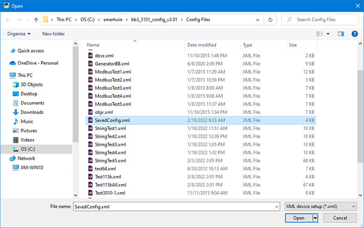
The same familiar file dialog will appear. Find the file you had just saved a few steps prior, select it and click Open.

Your saved configuration will now appear on the Object List page. This example is short - your actual configuration will likely fill the entire screen.
The red icons in the first column tell you that this information is not yet physically in the gateway. From the Object List page, click Write All. This will begin the process of sending the entire list of objects and their object mappings to the gateway device. As each object is sent, its icon turns green.

Upon completion of the Write All process, all of the icons on the Object List page will be green. The items on the Device page were already in sync from preceeding steps. The only remaining thing the tool doesn't know about is the Modbus page. If you go there and click the Read Device button on the far upper right, you should see the In Sync icon in the top right of the screen now turn green as well. The "In Sync" icon that appears in the upper right corner of every page is the global "everything is in sync". If red, it means there is at least one red icon on some page somewhere in the configuration tool.
Modbus is notorious for packing multiple data points into a single holding register, especially when a collection of status bits are just one bit each. When converting those status bits to some other protocol, especially BACnet, it is user unfriendly, if not downright non-functional, to put that collection of bits into something like a floating point Analog Input object. Thankfully, Babel Buster gateways can split a single holding register full of status bits into a collection of individual Binary objects.
The key to splitting a packed holding register into 16 different objects is to set up object maps that look like you are reading the same register 16 times. Internally, the Babel Buster optimizes the query. It sees you are reading the same register over and over, and does an actual read only once and then shares the data with all 16 object maps. Each time, the original Modbus data is processed according to the map's criteria, and the result is placed in the given target object. Each holding register can map to as many as 16 Binary objects, but you do not need to map all 16 bits. You can choose any number up to 16 and selectively mask only those bits into the appropriate number of objects.
Each of the object maps are set up the same as you would for reading any other unsigned 16-bit holding register. The only parameter you need to set differently is to put a non-zero value in the “mask” field. This mask is logically AND-ed with the Modbus data, that result is right justified, and then the final result is placed into the BACnet object if reading from Modbus. Reverse the process if writing to Modbus. You also need to check the box that says “Member of Packed Register” in the configuration tool software. This "Member" status tells the gateway to check the next object map and see if it references the same register, and share data with that object if so. If the "Pack Mixed Object Types" is selected, the gateway scans all object maps looking for more matching maps to share data with. The gateway will operate far more efficiently if you arrange the "Member of Packed Register" maps in sequetial order, but you can force it to scan all objects each time if there is some reason to, such as placing some bits in Binary objects but placing a multi-bit field in an Analog object.
The same masking tricks can be used to write a packed Modbus holding register. There is one additional parameter that can be useful when writing, namely the “fill” parameter. If the register contains a bit that should always be set no matter what, you use the same values that you would for mask, except put them in the “fill” window instead. Just like the “mask” is logically AND-ed with the data, the “fill” is logically OR-ed with the data before sending it out to the Modbus device.
Documentation tends to be slightly different for every Modbus device. But if your device packs multiple bits into a single holding register, the documentation will note up to 16 different items found at the same register number or address. The bits may be identified with “Bn” or “Dn” or just “bit n”. Most of the time, the least significant bit will be called bit 0 and the most significant will be bit 15. It is possible you could find reference to bit 1 through bit 16, in which case just subtract one from the number to reference the table below. For each of the 16 bit positions, the mask (or fill) will be as follows. These mask values are shown in hexadecimal, as is expected by the BB3-3101/3060 configuration tool.
B0/D0/bit 0 mask = 0001
B1/D1/bit 1 mask = 0002
B2/D2/bit 2 mask = 0004
B3/D3/bit 3 mask = 0008
B4/D4/bit 4 mask = 0010
B5/D5/bit 5 mask = 0020
B6/D6/bit 6 mask = 0040
B7/D7/bit 7 mask = 0080
B8/D8/bit 8 mask = 0100
B9/D9/bit 9 mask = 0200
B10/D10/bit 10 mask = 0400
B11/D11/bit 11 mask = 0800
B12/D12/bit 12 mask = 1000
B13/D13/bit 13 mask = 2000
B14/D14/bit 14 mask = 4000
B15/D15/bit 15 mask = 8000
Some Modbus devices also back two 8-bit values into a single 16-bit register. The two values will typically be documented as “high byte” and “low byte” or simply have “H” and “L” indicated. If you run into this scenario, the masking for bytes is as follows:
High byte mask = FF00
Low byte mask = 00FF
There have been a few instances of documenting packed bits in a 32-bit register. Although Modbus protocol is strictly 16-bit registers, some implementations force you to read pairs of registers. If your device documents 32 packed bits, then you would insert 0000 in front of each mask above, and the remainder of the list would be as follows:
B16/D16/bit 16 mask = 00010000
B17/D17/bit 17 mask = 00020000
B18/D18/bit 18 mask = 00040000
B19/D19/bit 19 mask = 00080000
B20/D20/bit 20 mask = 00100000
B21/D21/bit 21 mask = 00200000
B22/D22/bit 22 mask = 00400000
B23/D23/bit 23 mask = 00800000
B24/D24/bit 24 mask = 01000000
B25/D25/bit 25 mask = 02000000
B26/D26/bit 26 mask = 04000000
B27/D27/bit 27 mask = 08000000
B28/D28/bit 28 mask = 10000000
B29/D29/bit 29 mask = 20000000
B30/D30/bit 30 mask = 40000000
B31/D31/bit 31 mask = 80000000
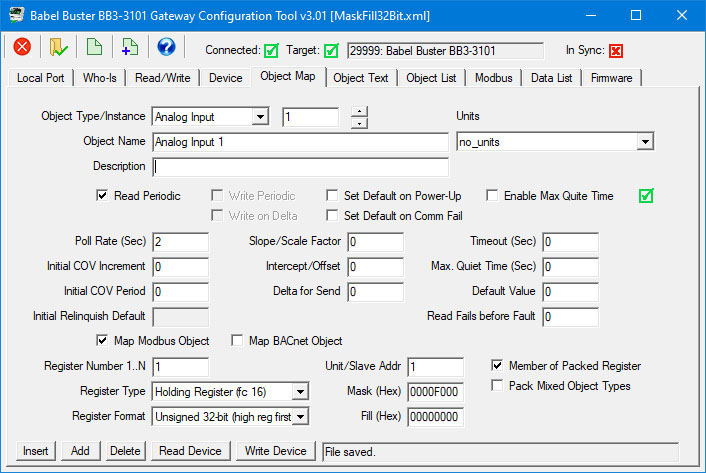
The following example shows picking bit 7 from 16-bit holding register 55, and placing its state in Binary Input 1.

If the Modbus register is a 32-bit register, then the mask and fill values expand to 32 bits each. The following example will pick out a 4-bit value from bits 12-15 of the 32-bit register at Modbus address 1 and place the value (which will be in the range of 0..15) in Analog Input 1.