
The Modbus page is where you configure the Modbus RTU port and check Modbus errors. Only the right half of the page is used for configuring Modbus. The left half is for diagnostics.
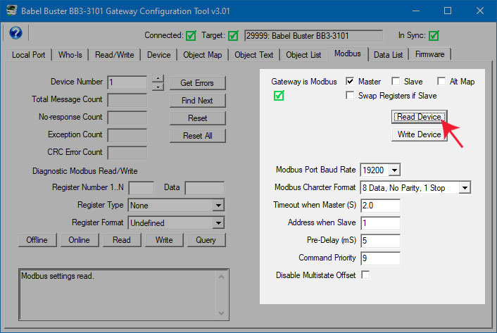
The Modbus port parameters that must be set for Modbus RTU operation are as follows.
| Master/Slave Mode | Check the applicable box to select desired mode of operation. In most cases, the Babel Buster gateway will be Modbus Master. The mode will change when Write Device is clicked. (It is suggested that you make all applicable changes first, then click Write Device.) |
| Alt Map | When the BB3-3101 gateway is being used as a Modbus slave, the Modbus register addresses are normally calculated as shown in Appendix D. If you prefer to use the alternate mapping scheme also talked about in Appendix D, then check this box. This selection only applies if the gateway is a Modbus slave. |
| Swap Registers if Slave | Registers containing data longer than 16 bits are actually multiple registers treated as a single data value. In the case of 32-bit data values (32-bit integer or floating point), two consecutive registers are used. However, the order in which the registers appear in the register map is not standardized. Selection of the register ordering is done in the object maps (see Section 8) when the gateway is operating as Modbus master. When the gateway is a Modbus slave, then the register ordering is set here and it applies to all slave registers in the gateway.
The BB3-3101 defaults to having the most significant data in the first register (lowest numbered register). If your Modbus master expects to read the least significant data first, then check "Swap Registers if Slave". If the data your Modbus master is receiving does not make any sense, try changing this "Swap" setting and see if you get better results. Remember that this only applies to 32-bit integer or floating point values. If your data is wrong for a 16-bit integer, your problem lies elsewhere. |
| Baud Rate | Standard baud rates from 1200 to 115,200 are supported. |
| Character Format | Modbus RTU is always required to be 8 data bits. The parity and number of stop bits may be selected here. |
| Timeout | Timeout applies only when the gateway is operating as Modbus master. This is the amount of time (in seconds, fractions to tenths supported) that the gateway will wait for the slave device to respond. If the gateway has not received a response within this time, it is counted as a timeout and the no-response error status is indicated.
Note that if Timeout when Master is zero, you will get nothing but 'no response' errors because the master is not waiting at all for any response from the slave device. |
| Address | Address applies only when the gateway is operation as Modbus slave. This is the address to which the gateway will respond on the RTU network. |
| Pre-Delay | Pre-Delay is the amount of time that the RS485 transmitter will be online before the start of the first character. It also provides a delay between queries in the event the gateway is too fast for other Modbus devices on the network. In most cases, some pre-delay is required, and experience has shown that 50 mS is a universal value that usually works.
If your Modbus slave responds to some queries, but gets seemingly random timeouts ("no response" errors), it may be missing some requests due to the gateway sending requests too fast. Increase the pre-delay when a slave is getting some successful replies, but intermittent timeouts with no other types of errors reported. |
| Command Priority | This priority is applied to commandable objects when written to by an external Modbus master when the BB3-3101 is functioning as a Modbus slave. The default is priority 10. Priority must be from 1 to 16, except 6 is reserved. |
| Disable Multistate Offset | BACnet protocol dictates that a Multistate object may not have a value of zero. Modbus registers often have a value of zero. By default, the BB3-3101 will translate from Modbus to BACnet Multistate with an offset of one so that Modbus zero is indicated as state 1 in the Multistate object. To disable this offset, check the Disable Multistate Offset box. See section 12.3 for additional discussion. |
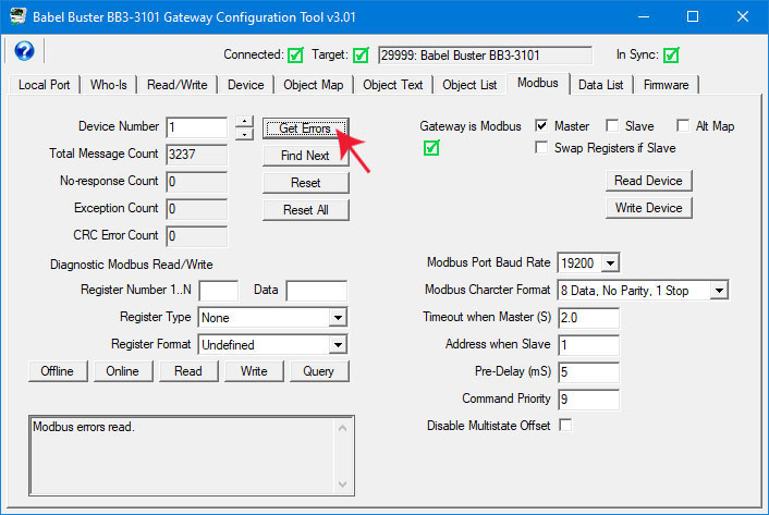
Enter or scroll to a desired Modbus slave address and click ‘Get Errors’ to see the message and error counts recorded by BB3-3101 for that device. Click ‘Find Next’ to have BB3-3101 automatically scan through all Modbus devices and report the next device that has non-zero error counts.
Click ‘Reset’ to clear the error counts and message count for the Modbus device whose address is currently displayed. Click ‘Reset All’ to clear all counts for all Modbus devices the BB3-3101 is polling.
Note: Total message count is a 32-bit count. No-response count is a 16-bit count and will stall at 65535. CRC and exception errors are 8-bit counts, and will therefore stall at 255. Normally you expect few if any errors once the system has been successfully commissioned, therefore space is not wasted on maintaining large counts. If you see a count of 255 exception errors, you know there were at least that many and likely more, but this will generally be observed only when first configuring the system and correcting configuration errors.
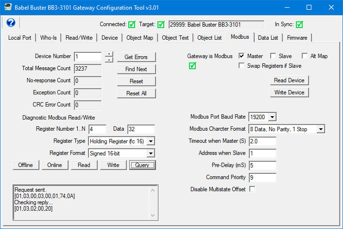
A very simple Modbus scanner is provided for diagnostic use, to see if your Modbus device is responding. The scanner uses the direct Modbus command pass-through, but does it in a fashion that is more user friendly. The scanner does not really ‘scan’ – we just call it that because the term scanner is widely used and understood by anyone with Modbus experience. In our instance, our ‘scanner’ sends a single request when you click Read or Write, and retrieves the corresponding query when you click Query.
Although the scanner will function at the same time gateway maps are generating Modbus traffic, it is easier to see error indications if you place the gateway in “offline” mode. The device LEDs (Request, Reply) will then only flash when you send a diagnostic command. The definition of “offline” is that read/write maps are not processed, but the device is functional in every other way. (Outside of this tool, the offline mode is achieved by writing NON_OPERATIONAL to the System Status property of the Device Object.)
To use the scanner, enter the register number you wish to read on the remote Modbus device (slave address given as Device Number above). Select a register type and format. Then click Read, or enter data in the data window and click Write. About a second or two later click Query to retrieve the result of the read or write. Commands and responses are shown in the log window at the bottom.
You will get an error in the reply if the Modbus device does not respond or any of several other problems exist. The following illustrates an exception reply because register 400 does not exist in this device:
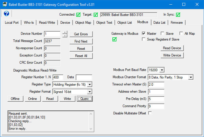
The first byte in the reply is slave address or unit number. The second byte is function code. If the most significant bit is set, it means there is an exception error. The MSB set shows up in hexadecimal format is the first digit being 8 (hex 83 returned for function code 3). The third byte, when the reply is an exception error, will be one of the error codes shown in the table below.
If you see "[empty]" immediately after "Checking reply..." it means the gateway is still waiting. We tend to assume still waiting for a reply, but it can mean waiting for our turn to send the request in the first place. If the gateway is configured with a significant number of points, click Offline to tell the gateway to stop polling other Modbus registers. You should then get either a reply, or the response that indicates an actual valid timeout occurred.
|
1
|
Illegal Function | The function code received in the query is not recognized by the slave or is not allowed by the slave. |
|
2
|
Illegal Data Address | The data address (register number) received in the query is not an allowed address for the slave, i.e., the register does not exist. If multiple registers were requested, at least one was not permitted.
This is the most common error users observe with the BB3-3101. It typically means configuration is incorrect - the gateway is attempting to request a register that does not exist in the Modbus slave. The most frequent incorrect register problem is entering 40001 for register number when you should enter just 1 and select holding register for type. |
|
3
|
Illegal Data Value | The value contained in the query's data field is not acceptable to the slave. |
|
4
|
Slave Device Failure | An unrecoverable error occurred. |
|
6
|
Slave Device Busy | The slave is engaged in processing a long-duration command. The master should try again later. |
|
0A
(hex) |
Gateway Path Unavailable | Gateway could not establish communication with target device. |
|
0B
(hex) |
Gateway Target Device Failed to Respond | Specialized use in conjunction with gateways, indicates no response was received from the target device. |
|
11
(hex) |
Gateway Target Device Failed to Respond | No response from slave, request timed out. |