
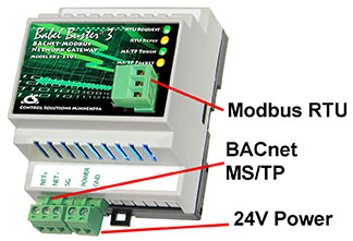
Wiring connections for the BB3-3101 are as follows:

Notes:
(1) Signal return required. Although EIA-485 (RS485) is thought of as a 2-wire network, you MUST include a third conductor connected to signal common at each device so that all devices are operating at close to the same signal reference.
(2) Cable shield terminated per wiring standards, most often connected to common or ground at field end. Do not connect Modbus and BACnet shields to signal common at the gateway if isolation is to be maintained.
(3) ESD protection depends on a ground suitable for dissipation of static discharge, necessary if not already provided by power common.
(4) These terminals are electrically isolated from all other terminals
(5) These terminals are electrically isolated from all other terminals IF the isolated Modbus port option is in use, otherwise referenced to Power Common.
(6) The various Common connections must be isolated from each other if communication port isolation is to be maintained. The power and shield grounds should be connected as specified by your network engineer, but typicall as noted in (2) above.
(7) Gateway may share common power supply with either the BACnet equipment or the Modbus equipment, but not both. Furthermore, if other equipment shares power with either BACnet or Modbus, then it is advisable to provide a separate isolated power supply for the gateway only.
Power-up LED behavior for BB2-3010 MS/TP gateway: All LEDs on front panel will turn on yellow or red for half a second, then all will turn on green for half a second. Then they will proceed to indicate as normally defined for the indicators.
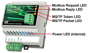
The LEDs will indicate BACnet traffic as indicated in the table below.
| BB3-3101 MS/TP LEDs | ||
| Mode | Token LED | Packet LED |
| Gateway is Client or Server |
Flash yellow each time the gateway sends a "poll for master". Flash green each time the token is passed. |
Flash green any time a packet is sent on the network. This can be either a request or a response to a request Flash red any time an error is detected. The error can be an error code reply, or timeout. The object reliability code will indicate which one it was. |
An MS/TP device that is functioning normally will always be at least passing the token, and usually polling for master periodically. The only time a device will not poll for master is if another device exists on the network with a MAC address only 1 greater than the gateway itself. It then just passes the token to that device without any intermediate polling for master.
Two particular indications of the MS/TP token LED are worth noting.
If the token LED appears to be on nearly solid yellow (or amber), this means the gateway is doing nothing but poll for token, which implies it is not finding any other devices on the network. You will see this any time you apply power to the gateway without connecting any network. If the network is connected, there is a problem with connections or port settings.
If the token LED is completely off and never flashes on, this means the gateway is hearing other traffic on the network, but just not connecting. An MS/TP device is required to "be quiet until spoken to". Therefore, if there is chatter on the network, but the gateway cannot find anything that is addressed to the gateway, it will remain quiet. This problem is usually the result of problems with port settings.
A gateway (or any MS/TP device) can alternate between the above two conditions. The "be quiet until spoken to" rule is up for grabs when the entire network is powered up simultaneously. Whoever wakes up first will be generating all the chatter whiile everybody else on the network listens.
If the token LED is very intermittent, flashes rapidly a few times (including green on the token LED), then is off completely for a period of time, this usually means it is trying to talk, thought it was talking or actually was for a bit, but something got out of sync. If there are duplicate device addresses on the network or mismatching Max Master settings, this will result in the appearance of intermittent communications.
Check your wiring. Noise on the line resulting from not following RS-485 wiring guidelines will result in communication problems ranging from no connection at all to frequent errors. Also be sure taht you have a ground connection between all devices on the network. The RS-485 network is not a 2-wire network. You need two data lines plus signal ground. If you consider cable shield a connection, then you need 4 connections.
The RTU request and reply LEDs will indicate Modbus traffic as indicated in the table below.
| Mode | Request LED | Reply LED |
| Gateway is Master | Flash yellow each time master (gateway) sends a request to a remote slave. | Flash green when master receives a good response.
Flash red when master receives exception message from slave, or if timed out with no response from slave (including CRC error in response which is discarded). |
| Gateway is Slave | Flash yellow each time slave (gateway) receives a request from external master. | Flash green when slave recognizes request as good/valid and sends a good reply.
Flash red when slave receives a request that results in replying with an exception, or there was a CRC error (RTU only) in the request. |
The MTX002 is an intelligent USB to MS/TP adapter - it is not a generic USB to RS-485 adapter. The MTX002 is itself a BACnet MS/TP device. Its purpose is to offload the token passing from the Windows PC since Windows often does not do a sufficiently accurate job of timing the token passing. In addition, PC hardware is incapable of operating at the 76800 baud rate common to MS/TP. The MTX002 does allow the PC to access MS/TP networks running at 76800 baud. Configuration software provided for the MS/TP gateways expects to use the MTX002 adapter, or access MS/TP via a BACnet IP to MS/TP router provided by the user.
Note that you must install the USB driver (see Appendix H) prior to attempting to use the MTX002.
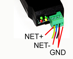
Connect the NET+ and NET- terminals to the corresponding MS/TP terminals on the gateway (or to +/- on the MS/TP network). Connect GND to network common.
DO NOT connect power to the terminal block on the adapter. The adapter gets its power from the USB port of your PC. The adapter only draws a very small amount of power, well below the limit provided by standard USB ports.
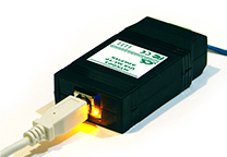
The yellow LED next to the USB connector will light up any time the PC recognizes this device. There is a blue power LED inside the adapter visible by looking into the adapter through the slot next to the USB adapter. The power LED should always be on if connected to the PC. The yellow LED will only come on when recognized by PC software.
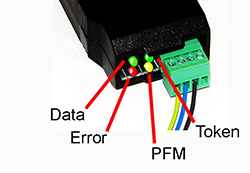
The LEDs next to the terminal block indicate network traffic on the MS/TP network.
The Token LED flashes green each time the adapter passes the token. The adapter functions as another MS/TP device on the network, and gets into the token passing loop just like any other MS/TP device.
The PFM LED flashes yellow each time the adapter sends a Poll For Master (PFM).
The Data LED flashes green each time a good packet other than token or PFM is received, or a packet other than token or PFM is sent, by the adapter.
The Error LED flashes each time a valid packet is received by the adapter, but resulted in an error. The Error LED can also indicate a timeout waiting for the slave device to respond (typically the device being configured).
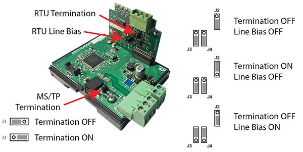
Enable line termination only when this device is placed at the end of the network. Termination should only be enabled at two points on the network, and these two points must be specifically the end points.
Enable line bias when needed. Line bias should only be enabled at one point on the network, and does not have to be the end point. Line bias holds the line in a known neutral state when no devices are transmitting. Without bias, the transition from offline to online by a transmitter can look like a false start bit and cause loss of communication.
The line conditioning options are enabled when the respective shunt is moved to the position indicated by the white block next to the 3-pin header. Putting the shunt on the opposite 2 pins disables the option, and is simply a place to store the shunt.
Termination header locations for BB3-3101 with standard non-isolated Modbus RTU port:
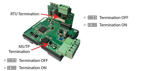
Termination header locations for BB3-3101 with optional isolated Modbus RTU port:
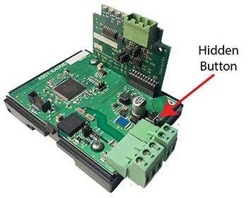
There is a hidden button used to restore factory defaults. The button is shown with the cover removed in the picture below so you can see where it is, but it is not necessary to remove the cover to press the button. Simply press on the plastic tab next to the terminal block and you should feel a light click.
There are two "codes" for restoring factory default.
Code 1: Reset communication parameters, but leave configuration intact.
Code 2: Reset communication parameters and erase all configuration.
Press and hold the button until you see code 1 flashing. If you wish to perform code 1, release the button while code 1 is flashing. Otherwise continue to hold the button until you see code 2 flashing and then release the button. If you do not release the button while code 2 is flashing, it will return to code 1 in a few seconds, and the codes will continue to alternate for as long as you hold the button down.
Upon releasing the button, you will see the code confirmation flashing. Press the button again to cancel the action. You must do the cancel within the next few seconds, otherwise the action will be performed. If you do not cancel the action, the action will be performed in a few seconds.
The LEDs that normally show MS/TP and Modbus traffic are temporarily used to display these codes while the reset is pending.
Code 1: Yellow/amber LEDs flash once and then pause (and then repeat).
Code 2: Red LEDs flash twice and then pause (and then repeat).
Confirmation: All LEDs flash green showing either code 1 or code 2 (one or two flashes followed by a pause, and then repeat).