
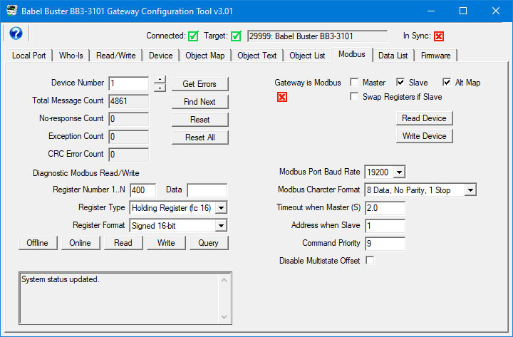
The BB3-3101 is put into slave mode by checking the Slave check box on the Modbus page of the configuration tool, and then clicking Write Device. In slave mode, the object maps are only used to define polling of other BACnet devices. You do not create any Modbus maps. The Modbus registers are pre-defined and fixed. You only need to map BACnet objects so that BACnet data is exchanged between the fixed Modbus registers and the remote BACnet devices. The fixed Modbus registers are really just a means of accessing the BACnet objects in the BB3-3101, and the means of access amounts to calculating a specific register number that points to one of the BACnet objects. The Modbus registers can only access the Present Value property of the BACnet objects that are maintained by the BB3-3101.
The BB3-3101 may have a total of 1024 BACnet objects; however, as a Modbus slave, you can only address a maximum of 500 of any one type of object. So, for example, if you wanted to monitor 1000 BACnet analog values, you might use 500 Analog Inputs and 500 Analog Value objects. This limitation is due to the way in which Modbus register numbers are calulated as derived from BACnet object type and instance.
Modbus register numbers for accessing data objects in the BB3-3101 are calculated. The register number for binary and multi-state objects is R=T*1000+I where T is the BACnet Object Type, and I is the instance (R is the resulting register number). The register number for analog objects, because they must be read as a register pair, is R=T*1000+I*2-1 (R is the first register number in the pair). Register numbers start at 1. To create a raw address, subtract 1 from the register number.
Analog objects should be read as input registers or holding registers, and can only be written as holding registers. Binary and multi-state objects can be read as any register type (coil, discrete, input register, holding register), and can be written as coil or holding register.
Analog objects are always floating point data read as a register pair with most significant register first unless the Swap box is checked on the Modbus page in the configuration tool. Attempting to read or write an Analog object as a single register will produce an error.
Object types that may be used in Modbus register number calculation (as "T") are:
0 - Analog Input
1 - Analog Output
2 - Analog Value
3 - Binary Input
4 - Binary Output
5 - Binary Value
13 - Multistate Input
14 - Multistate Output
19 - Multistate Value
The reliability code of an object may be read as an unsigned integer by adding 20,000 to the calculated register number.
The following function codes are used by BB3-3101 as Modbus master, and are also recognized by BB3-3101 when functioning as a slave.
1 - Read Coil
2 - Read Discrete Input
3 - Read Holding Registers
4 - Read Input Registers
5 - Write Single Coil
6 - Write Single Holding Register
15 - Write Multiple Coils
16 - Write Multiple Holding Registers
You can read or write Binary or Multistate objects as Modbus Coils. A coil on/off will correspond to Binary states on/off. A coil state of "off" will be a Multistate value of 1, and a coil state of "on" will be a Multistate value of 2. Accessing Multistate objects as coils is not particularly useful but is permitted.
You can read Binary or Multistate objects as Modbus Discrete Inputs. The values will be as noted for Coils.
Due to the fact that Analog objects map to register pairs, you cannot access Analog objects as coils or discrete inputs.
You can read Analog objects as Modbus Input Registers. You can read or write Analog objects as Modbus Holding Registers. In both cases, you must read or write register pairs for each object, and the data will be IEEE 754 floating point.
You can read Binary or Multistate objects as Modbus Input Registers but must read these as 16-bit integer values.
You can read or write Binary or Multistate objects as Modbus Holding Registers and must read or write these objects as 16-bit integer values.
Alternate Map applies only if you are using the BB3-3101 as a Modbus slave. Although Modbus protocol specification provides for up to 65,535 holding registers (and 65,535 of each type of register), some older Modbus masters can only access 9,999 registers and their holding register range is usually documented as 40001 through 49999 (also known as Modicon notation). If your Modbus master cannot access the full range of registers, you will need to use the alternate mapping discussed here.
Enable the alternate Modbus slave map by checking the Alt Map box as illustrated below. This box can only be checked if you have also checked Slave.
If you are using the BB3-3101 as a Modbus slave, then it would have to mean that all of your object maps are reading (or writing) MS/TP slave devices. Once you have allocated the desired number of objects on the Device tab, and configured your maps on the Object Map tab, go to the Object List view. Scroll the screen left, or expand the view by dragging the right border to stretch the screen. This will reveal the Alt Map column. This column is simply provided as a reference list and assigns a sequential number to each object map in the list without respect to type.
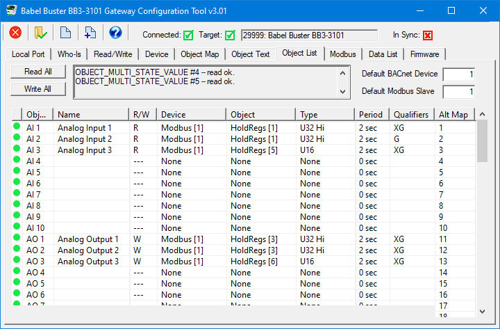
You will use the Alt Map reference number to calculate your Modbus register numbers. The Alt Map method only provides access to the first 500 objects on the list. In this mode, you are limited to accessing only 500 objects total. This limit will keep addressing within the confines of Modicon register numbering.
If your Modbus master does not make reference to the first holding register at 40001, but talks about address 0, or register 1, these all point to the same first holding register. The first holding register is address 0 on the wire, but is often documented as register 1, and in older documentation (or new documentation following old Modicon conventions), the first holding register will be listed as 40001.
Register number calculations are performed as noted in the following table. Since the restriction on number of accessible registers is most often associated with older equipment, we will use Modicon notation here since that same older equipment most likely uses this notation (i.e. 40001 is the first holding register).
You may read any of the BACnet objects mapped using any of the following data formats: Integer (16-bit), Unsigned integer (16-bit), Double signed integer (32-bit), Floating point (IEEE-754 32-bit). The different formats are read by using different address ranges to access the same object. Calculate addresses as illustrated in the following table, where M is the number in the Alt Map column above.
|
Alt Map |
Signed |
Unsigned |
Double |
Floating |
Reliability |
|
Formula |
M + 40000 |
M + 41000 |
M*2 + 42000 |
M*2 + 43000 |
M + 44000 |
|
Object 1 (M=1) |
40001 |
41001 |
42002 |
43002 |
44001 |
|
Object 2 (M=2) |
40002 |
41002 |
42004 |
43004 |
44002 |
|
Object 3 (M=3) |
40003 |
41003 |
42006 |
43006 |
44003 |
The access rules are different when using ALT Mapping.
You can read or write any object type referenced as any Modbus register type when accessing signed or unsigned integer (16-bit). When accessing the object as double integer (32-bit) or floating point (also 32-bit), you can only access these as Modbus Input or Holding Registers, and must access these as register pairs.
To illustrate the meaning of the above paragraph, you can read or write an Analog object as a Modbus Coil when using ALT mapping and referencing an integer register number. This is permitted, although not particularly useful as the only possible values you can write to the Analog object are zero and one when accessing it as a coil. The more practical use of ALT mapping for accessing an Analog object would be to access that Analog object as a 16-bit integer value (single Modbus Holding register), and this can be useful for a PLC that does not do well with floating point values.
The BB3-3101 can be configured as a Modbus slave and BACnet client, thus giving some other Modbus device like a PLC control over BACnet output objects via the BB3-3101 gateway. Because Modbus knows nothing about “relinquish” (or command priorities), there is no way to write to a Modbus register such that the BACnet object will relinquish a commandable priority level. When the BB3-3101 is acting as a Modbus slave, writing to holding register addresses that map to Output objects will result in the Modbus command priority being set. But there is no direct way to relinquish that command priority.
The remedy to this problem is that phantom registers have been added which are recognized only by the Modbus slave. The phantom registers are accessible by calculating the slave register number of the Output object as defined above, and then adding 40,000 to the holding register number. If using the “ALT” mapping, add 5,000 to the ALT map register number instead. Writing any value to this register number will relinquish the Modbus command priority for that object. An exception will be returned if you try to relinquish a non-commandable object.
In order to give Modbus full control over a commandable object in some other BACnet device, it is necessary to program your Modbus master to write to one holding register to set the output, and write to a different register (the phantom register) to relinquish the output. The addresses you use will be derived from the local Output object number you choose as the local object in the gateway. To cause that object to then be transmitted to the remote BACnet device, you need to set up a client write map as illustrated in section 8.3.