
|
Control Solutions devices originally came with a predefined set of local registers that were accessible externally as Modbus registers. Newer models take a completely different approach to defining registers. When you first take the ValuPoint out of the box, it has no registers except for the initial set of registers assigned to the physical I/O points. You get to create remaining registers as you need them, and several data formats are supported, from 16-bit to 64-bit, both integer and floating point.
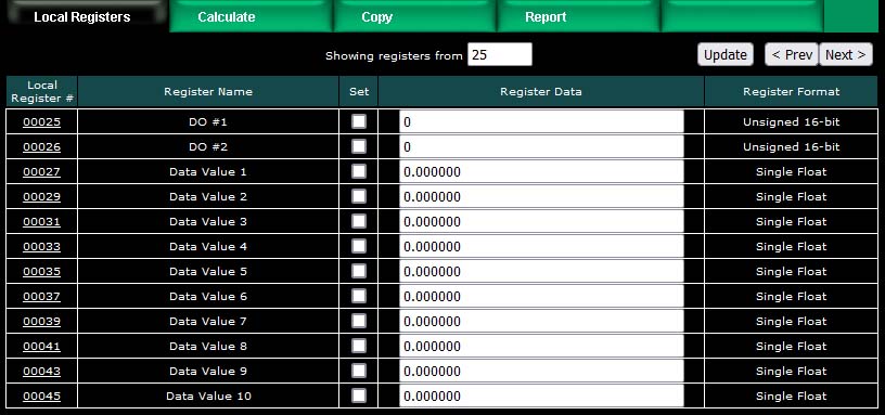
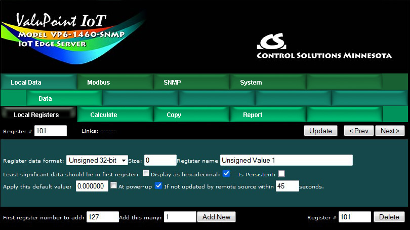
Your first visit to the Local Registers page will be as illustrated below.
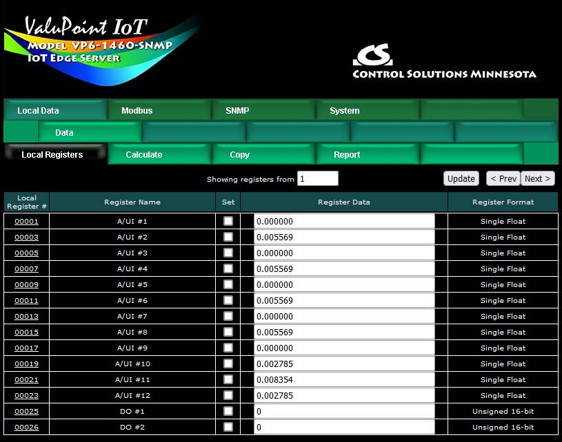
You do not need to create any additional registers if you will only be using the I/O points. To begin the process of creating additional registers, click on the last register number on the list. Later on, click on the register number at the end of the list to add more, or click anywhere in the middle of the list if there are gaps in the register number sequence that you would like to fill.
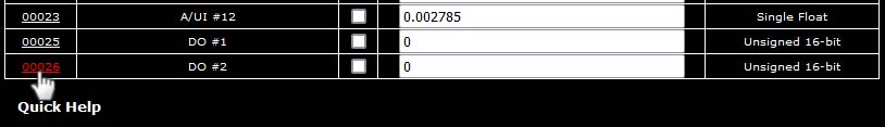
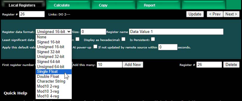
Upon clicking a register number, the register detail will be displayed. This can be either detailed configuration of an existing register, or detail about new registers you are about to add. The only time you can select the data format is when adding new registers. Once the registers are created, the data format cannot be changed because this impacts how many Modbus registers are actually used. If you had a set of 16-bit registers defined, and wanted to change one of them to 32-bit, it would cause all of the remaining registers to be renumbered if such a change was allowed. While this may seem harmless at first, it becomes a huge mess trying to keep track of where in all the rules the existing numbers needed to get changed. Therefore, such changes are prohibited.
Select the data format for the new registers to be created. The designations Signed and Unsigned refer to integers. Float refers to IEEE 754 floating point format. Character string refers to a series of registers with two ASCII characters per 16-bit register. Mod10 refers to a format unique to Schneider Electric power meters (refer to Schneider Electric documentation for a definition of those formats).
IMPORTANT: Modbus protocol knows holding registers (or input registers) to simply be a 16-bit piece of data. The protocol knows nothing about signed or unsigned integer - that interpretation is up to you. The 16 bits may even be a collection of 16 status flags. If a register is defined in the ValuPoint as anything bigger than 16 bits, it is actually a pair (or series of 2 or more) of 16-bit registers. Again, Modbus protocol does not know anything about floating point, character strings, etc. Modbus only knows how to send 16 bits of something at a time when function codes reference a holding register or input register. Modbus only knows how to send 1 bit at a time if referenced as a coil or discrete input. It is up to the Modbus master to be smart enough to ask for 2 registers at a time if it knows it wants to read a 32-bit value.
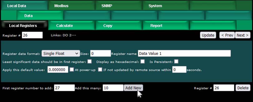
In addition to selecting data format for creating new registers, provide a temporary register name. You can change this later, but it is usually helpful to start with something for a name, and it is suggested that the name ends with a number. The reason why is illustrated shortly.
Modbus protocol is strict about 16-bit increments of data for holding registers. However, when register pairs (or quads) are used to hold a 32-bit (or 64-bit) value, the order in which those registers are interpreted is not defined by any standard. It is up to you to keep track of that. ValuPoint supports interoperability with other Modbus devices by letting you specify what order should be used internally. If the least significant data should appear in the first (or lower numbered) register, then check the box that says "Least significant data should be in first register" either when creating the register, or later by reconfiguring the existing register.
When first creating registers, you do not need to enter any of the default information on the last line. (You can, but don't have to.) The size only applies when creating character string variables (illustrated later, below).
The first register number to add, indicated at the bottom of the page, will be the first available register slot that is not yet assigned. You can enter some different number here. It is not required to create registers in contiguous order. You can jump around, as long as registers don't try to overlap. Select a number of registers to create, and click Add New. If you attempt to add registers that overlap existing registers, the allocation algorithm will find an available slot for you and fill that instead. The maximum possible register number will be the count indicated on the Resources page as Local Modbus Register Pool Size.
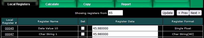
We have now created 10 new floating point registers. The important thing to observe here is the register numbers in the first column. Remember that Modbus protocol assigns register numbers (or addresses) in 16-bit increments. Since single precision floating point registers are 32-bit registers, each floating point value occupies 2 spots in the Modbus register map. The local register number assignments reflect this fact.
Note that the name given in the screen above was "Data Value 1" but our series of 10 new registers came up with 10 sequential names. If the last thing to appear in the name given when assigning new registers is a number, this value will be incremented by one in the name of each successive new register.
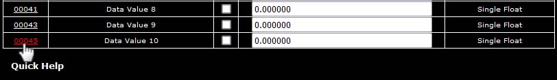
Now let's proceed to add some character strings. Click on the last register number assigned thus far to open the register detail page.
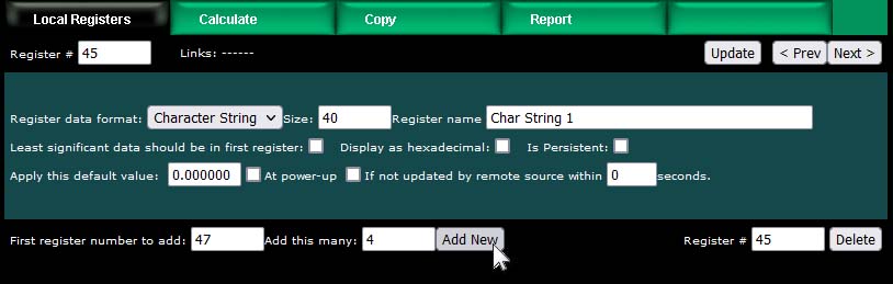
Select Character String for data format. This is the one time a size must be specified. In the example below, we are going to allocate 40-character strings. This means that each "register" will actually be a series of 20 Modbus registers (two ASCII characters per register). The character string processing assumes that any display device used in conjunction with these registers will display the high order byte on the left and low order byte on the right in any given 2-character portion of the display screen. This is consistent with display devices that have been tested with ValuPoint.
After clicking Add New, we now see our character string registers in our register list (click on the Local Registers tab to get back to the register list). Note that the register numbers increment by 20 to accommodate our 40-character strings.

You can set the character strings from the web page,. The strings can be read or written by Modbus as a series of registers with 2 characters per register.
The first 26 registers in the ValuPoint are permanently assigned to the physical I/O points. Those register numbers are illustrated in the first screen shot in Section 4.1 above.
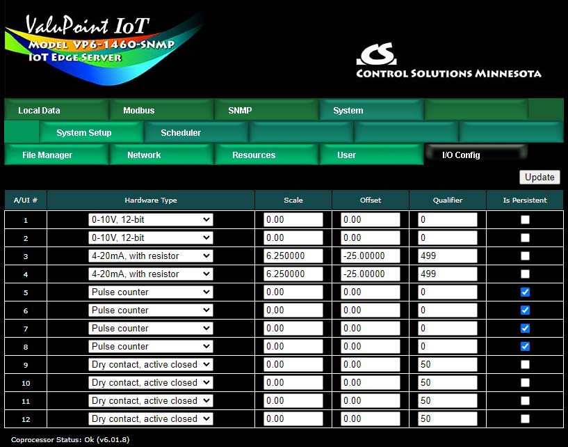
The relay outputs do not require any configuration. The analog/universal inputs do require configuration on the I/O Config page. Select the desired input type and enter additional parameters as applicable.
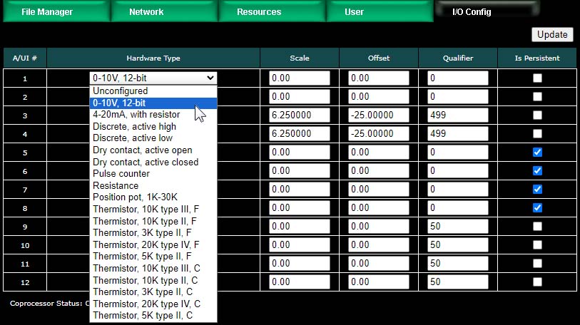
The A/UI inputs may function as any of the following:
0-10V, 12-bit resolution (reading is Volts)
4-20mA, with resistor (reading is mA)
Discrete, active high
Discrete, active low
Dry contact, active open
Dry contact, active closed
Pulse counter
Resistance (reading is ohms)
Position pot, 1K-30K (reading is percentage)
Thermistor, 10K type III, F (readings in degrees for all of following)
Thermistor, 10K type II, F
Thermistor, 3K type II, F
Thermistor, 20K type IV, F
Thermistor, 5K type II, F
Thermistor, 10K type III, C
Thermistor, 10K type II, C
Thermistor, 3K type II, C
Thermistor, 20K type IV, C
Thermistor, 5K type II, C
Dedicated hardware is available for pulse counting on channels 5, 6, 7, and 8. The only limiting factor on maximum pulse rate on these inputs is the noise filtering on the inputs. The inputs have been verified to count at up to 1kHz provided the signal amplitude is sufficient. Pulse counting is supported on the remaining input channels, but the counting is done by software and therefore the rate is limited to about 2Hz.
The 4-20mA setting is used as a label since that is most common. However, the input is actually going to be 0-20mA, and the register value for that range will be 0..20. The scale and offset can be used to convert 4-20mA to a 0-100% value by using scale = 6.25 and offset = -25. A dropping resistor of 500 ohms will use the full 10 volt input range. A dropping resistor of 250 ohms can be used - it will simply provide less resolution.
Scale – Scaling applies the formula y=mx+b. When reading from a hardware input, the raw data as read is multiplied by the scale factor, then the offset is added to produce the resulting register value. NOTE: If no scale factor is given (zero is entered), no scaling will be done, as if scale=1 and offset=0.
Offset – The offset portion of the scaling as noted above.
Qualifier – Enter the configuration qualifier value, if applicable, for the selected configuration. Qualifiers are required only in the following modes:
4-20mA mode: The qualifier is the resistance in ohms of the dropping resistor used to convert the current to voltage. An external resistor must be provided, connected between the A/UI input and ground/common. The resistor needs to be 1/2 watt (2 watt to withstand 24V power), and is left external simply because miswiring the 4-20mA sensor can easily apply 24V power directly to the input and cause the dropping resistor to heat up and possibly fail. The external resistor is simple to replace, whereas an internal resistor on a circuit board would be more trouble to replace.
Discrete and Dry Contact modes: The qualifier is a threshold between 1% and 99% at which the input should trip from off to on or vice versa. The A/UI inputs are specified as 0-10V inputs. Therefore, since discrete inputs are sampled as analog values and compared to a threshold, the qualifier here is a percentage of 10V for the trip point. A value of 50% will mean a threshold of around 5V.
Position Pot: Position is simply a different interpretation of resistance measurement. The value resulting from position pot measurement will be a percentage from 0% to 100%, but this percentage will be a ratio based on the resistance value in ohms provided as the qualifier.
There are a couple of features that you may go back and change at any time after registers are created.
You may select hexadecimal display of data. This only applies to display on the local web pages, and does not change what Modbus sees externally (Modbus only sees a collection of bits, and that fact never changes). Hexadecimal display of a floating point value is probably meaningless, but hexadecimal display of registers containing a set of status bits packed into a single register is often easier to interpret when displayed as hexadecimal.
You have the option of applying a default value under two conditions: (1) Automatically at power-up; (2) Any time this register is not updated by some remote source within the timeout given (this assumes the ValuPoint is acting as a slave or server).
If this register is being used to hold a value provided by some other device acting as master, and you want a way of externally detecting when that device has failed to communicate, you can cause a "flag" value to appear in this register when a new value has not been received within the given timeout period.
Applying a default at power-up is potentially useful if you want this server to always write a certain value to some other Modbus slave any time the system wakes up.
The other use for default at power-up is when you need to use a constant value in a calculate rule. Set aside a register whose only purpose is to hold this constant for later use.
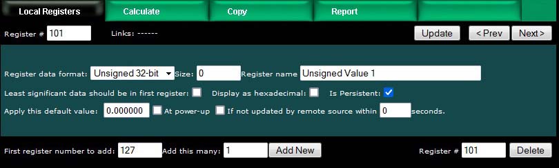
The "Is Persistent" option means this register will retain its most recent value through a power outage or restart, with time delay restrictions. The persistent selection does not take effect until the Reset Persistent Data button is clicked on the Resources page.
The persistent data is stored in non-volatile memory which has a life expectancy of 4 million write cycles. However, if the data is written too frequently, the memory will still reach its end of life prematurely. Therefore, to extend the life of the EEPROM, persistent data is only updated once every 15 minutes. If the data has not been written in the past 15 minutes, new data will be written to EEPROM immediately. Otherwise writing to EEPROM will be delayed until the expiration of the timer for that register.
The most recently stored data is read from EEPROM and placed into the local register at startup.
The ValuPoint includes the ability to do simple calculations based on simple template rules. Select the operation, one or two operands as applicable, and a register to place the result in. Operations like "multiply" will use registers A "and" B. Operations like "sum" can add up the contents of a series of registers by selecting "thru" instead of "and".
These template rules can be useful for doing minor data manipulation or testing for purposes of enabling rules, or for generating SNMP traps.
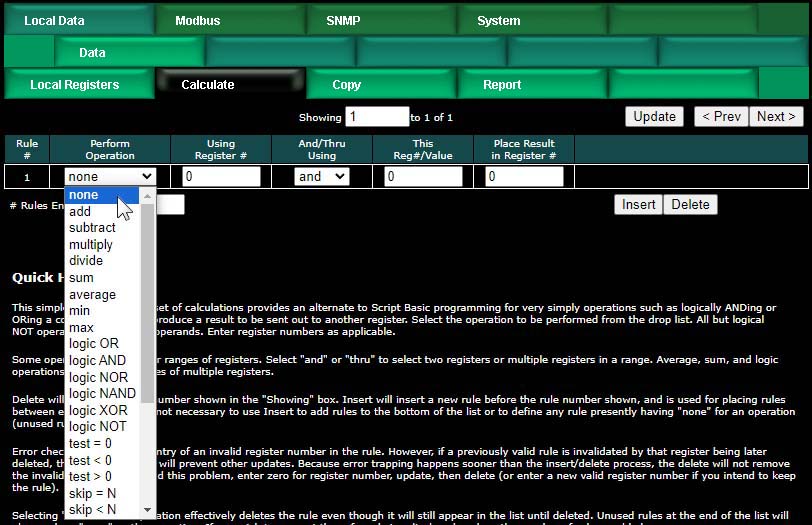
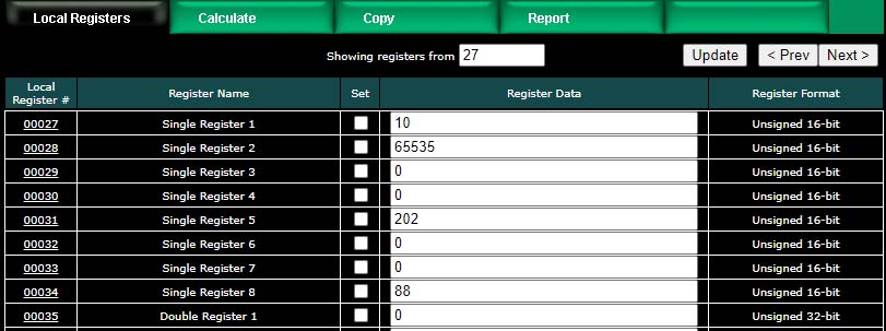
Here is an example of a template rule that multiplies register 27 by register 29 and places the result in register 31.
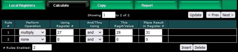
If registers 27 and 28 contain the values shown below, then the result shown in register 31 would be expected.

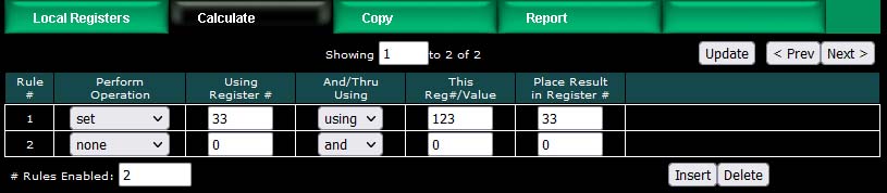
Constants may be introduced into the calculation by reserving a register to hold that constant, and then configuring it to apply a default value at power-up. This default value should be the constant you wish to include in a calculation.
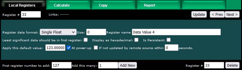
The other option is to use the set operation, but the value is limited to unsigned integer with the set operation. The example illustrated below will set register 33 to a value of 123.
Operations available on two or more registers using 'and' or 'thru':
| add | Add two registers |
| subtract | Subtract second register from first |
| multiply | Multiply two registers |
| divide | Divide first register by second |
| sum | Sum two or more registers |
| average | Average two or more registers |
| min | Find lowest value among two or more registers |
| max | Find highest value among two or more registers |
| logic OR | Logically OR two or more registers |
| logic AND | Logically AND two or more registers |
| logic NOR | Logically NOR two or more registers |
| logic NAND | Logically NAND two or more registers |
| logic XOR | Logically Exclusive-OR two registers |
Operations available on one register:
| logic NOT | Generate bit-wise negation of register |
| test = 0 | Set result to 'true' if register is zero |
| test < 0 | Set result to 'true' if register is less than zero |
| test > 0 | Set result to 'true' if register is greater than zero |
Operations available on one register 'using' a given value:
| set | Set register to given value (unsigned 32-bit integer) |
| skip = N | Skip next operation if register is equal to given value |
| skip < N | Skip next operation if register is less than given value |
| skip > N | Skip next operation if register is greater than given value |
| comp = N | Compare, set result 'true' if register is equal to given value |
| comp < N | Compare, set result 'true' if register is less than given value |
| comp > N | Compare, set result 'true' if register is greater than given value |
| pack | Perform Pack operation (see text) |
| fill | Perform Fill operation (see text) |
| unpack | Perform Unpack operation (see text) |
| shift left | Shift content of register left by 'using' number of bits |
| shift right | Shift content of register right by 'using' number of bits |
Operations "using" a given value will have an unsigned integer value in the "This Reg#/Value" column rather than a register number. These values will be displayed as integer for most operations, but will be displayed in hexadecimal for pack, fill, and unpack operations since these operate primarily on bit mask values.
The result of a test or compare will be zero if false, or one(s) if true. The true value will be the maximum unsigned 16-bit or 32-bit integer value if the result register is integer. If displayed as unsigned hexadecimal, it will be FFFF or FFFFFFFF. Displayed as signed 16-bit integer, "true" will be 32767. If the result register is floating point, then "true" will just be 1.0. The purpose of using FFFF for unsigned integer true is so that the result is useful as a bitmask.
Pack and fill are used for packing multiple local registers into a single register for purposes of emulating existing equipment when the ValuPoint is functioning as a Modbus server (slave). When pack and fill are used, "using" should be selected, and the second entry is a hexadecimal mask or fill value.
The pack mask is both a bit mask and position indicator. To calculate the contribution of a given calculate rule, the mask is right shifted until the least significant bit is nonzero, then this shifted mask is logically AND-ed with the local register content. The resulting masked value is then left shifted back to the original mask position. This final shifted result is then logically OR-ed into the result register (after first clearing the bits in the affected position of the result register).
Fill is simple - it simply logically OR's the bit mask into the result register.
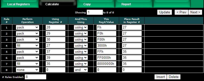
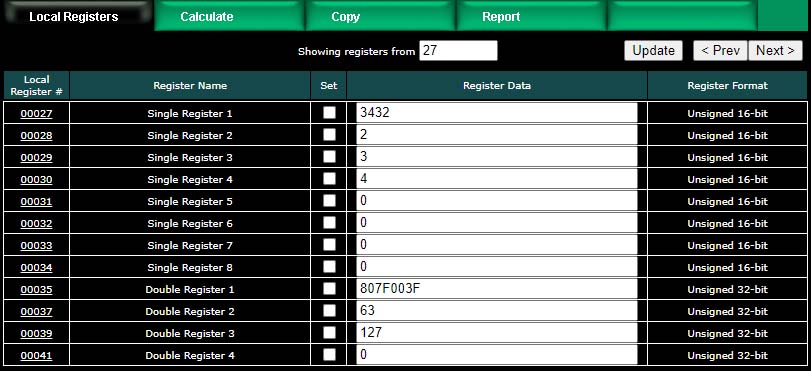
The example below shows the content of result registers 27 and 35 using the above calculate rules and the local register values shown. The contents of registers 28, 29, and 30 are packed into register 27. The contents of registers 37 and 39 are packed into 35 (all 32-bit register pairs).
This process can be reversed using the "unpack" operation. The following calculate rules exactly reverse the above packing operations (discarding fill in this case).
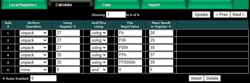
Register 27 is unpacked into registers 28, 29 and 30. Register 35 is unpacked into registers 37 and 39 (all 32-bit register pairs).
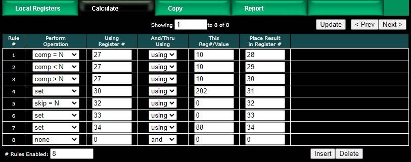
The next two screen shots illustrate compare, set, and skip operations. Rule 5 says that rule 6 will not be executed if register 32 contains a zero. If register 32 is not equal to zero, then rule 6 will be executed.
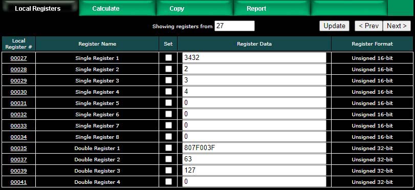
Register values for examples using the above operations are illustrated below.
The copy rules provide a means of simply copying the content of one register to another.
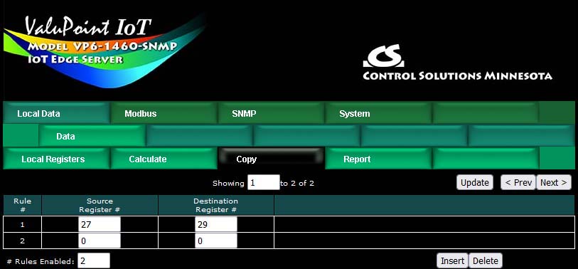
The above rule would cause the following data copy to occur:
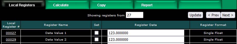
Here, however, is a much more interesting use of the copy rule:
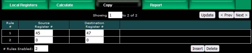
The above rule would cause the following copy to happen. Note that "copy" also means data reformatting. Therefore, if you need to convert a number to a character string (or vice versa), simply copy it from one register to the other. In this example, our copy rule is converting floating point to an ASCII string ready to be sent to a display device.
String conversion is not the only conversion you can do. If you need to convert floating point to integer, or vice versa, the copy rule will also do that. Note, however, that if you need to read an integer from a remote Modbus slave but want the result stored locally as floating point, you can do that conversion as part of the read map and do not need a separate copy rule to accomplish that conversion.
The ValuPoint read maps include the ability to set a default value upon 'n' read fails, meaning that if the ValuPoint gets an error 'n' times attempting to read that point, it will automatically set the corresponding local register to the given default value to indicate the problem. This indication applies on a point by point basis, but of course any one point can be used as an indication that the entire device may be offline.
The ValuPoint also includes the ability to report device errors to an assigned status register rather than rely on default values. This reporting is configured on the Report page.
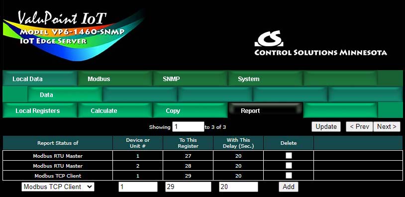
This optional list allows reporting device errors as register values to make it easier to monitor communication failures. The length of the list is variable. To add to the list, select the type of device to report on, select the device instance or unit number to report on, and select a register in which to put the status indication. Enter a delay if desired, and then click Add.
The delay is optional. If zero, there is no delay. If some number of seconds is entered, then the error condition will not be reported until this time period expires. If the error clears before the time is up, then the error is never reported. This is useful for spurious errors that would result in nuisance indications.
To remove a report from the list, check the box in the Delete column and then click Update. Click Prev or Next to scroll through the list.
Error codes placed into the reporting register will be as follows:
0 = No error
1 = Timeout, no response from remote device
2 = Error message received from remote device (e.g. Modbus exception)
3 = Line fault (e.g. CRC error, socket connection error, etc)
Once a Timeout error indication has been set (following delay if applicable), it will automatically return to zero upon the next successful communication with that device.
Once either the error message or line fault indication has been set, following delay if applicable, communication must continue free of this same error condition for at least the same delay period before the indication will be reset to zero. If an error message (e.g. Modbus exception) is reported for one data point, but multiple others are error free, then the one error would be hidden without this delay before reset. Ideally, this delay period should be at least as great as the poll period for the slowest point mapped.