
Your configured objects can be viewed on the Object List page. The appearance will be slightly different between Modbus and BACnet. If you have selected VP3-TM10 or VP3-TM60, then the protocol column will contain Modbus register information. If you have selected VP3-TM30 or VP3-TM70, then the protocol column will contain BACnet object information.
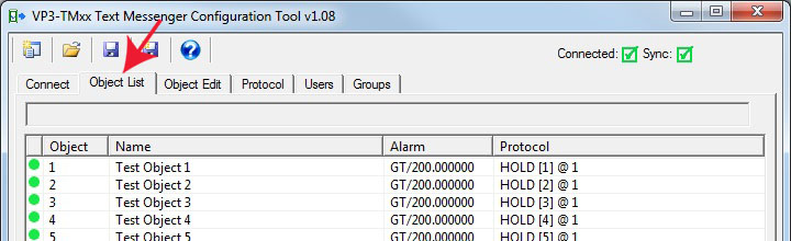
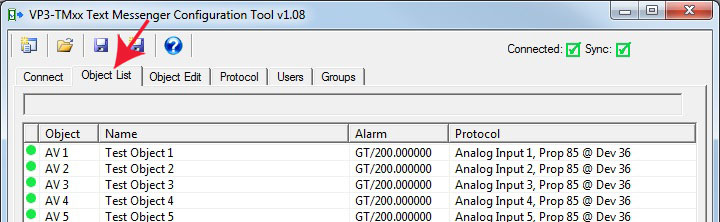
Double click on any line in the list to jump to the Object Edit page for that object. The icon in the first column will be green if this object is "in sync" with the device, meaning what you see on the screen is what is in the device. The icon will be red if changes have been made that have not been written to the VP3-TM yet.
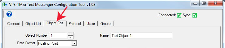
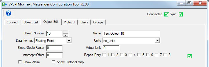
Changes to object configuration are made on the Object Edit page. Go here and select an object number or scroll through the list. The many parameters that may be entered here are discussed throughout the remainder of this section of the user guide.

If you are connected to a VP3-TM and you are ready to send your configuration changes to the VP3-TM for the object displayed on the screen, click Write Device at the bottom of the Object Edit page. If you want to read what is in the device for this object, click Read Device.
The minimum requirement for configuring a data object is to select a data format and give it a name. There are only slight variations between the Modbus and BACnet versions when it comes to configuring a data object.
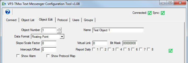
Changes to the selected object are made in the configuration tool by entering numbers, selecting items from a drop down list, or checking boxes. This on-screen template translates into configuration commands sent to the VP3-TM. These same commands can be sent via the command console (see Section 6.3) or via SMS. Throughout the remainder of this section, the configuration command parameters will be presented in command form, but the definition of those parameters will apply to the on-screen template as well.
When an object configuration command is sent to the VP3-TM, it always starts with "obj N" where the "obj" identifies the fact that we are sending object configuration, and N is the object number we want to configure.
The “obj” tag is delimited by a space. The first item following the space must always be the object number to be configured. After that, one or more configuration fields are delimited by commas. Each field starts with a tag name, followed by the “=” sign. Everything after “=” up to the next comma will be taken as the value for that tag. If commas are to be embedded in a name or message string, then the entire string must be enclosed within double quote marks, e.g. “This is one, two, three in a name”. The quotes should be plain quotes, not “fancy” quotes created by Word like those around “fancy”. Use a simpler text editor like just Notepad if creating a script file that will be copied to the device later.
Example:
obj 1,name=”Engine Temp”,datatype=FLOAT,scale=1.8,offset=32
It is not necessary to include a space after the comma, but may be inserted if desired for readability. Spaces after the comma will be discarded.
The VP3-TM provides 100 internal data objects. These may be mapped to read Modbus registers in an external device, read BACnet objects in an external device, or be written by an external master/client. Valid object numbers are 1-100.
Parameters are as follows.
obj1,name=”Engine Temp”
Sets object name (ASCII string up to 39 characters). The name must be a quoted string.
obj 1,datatype=FLOAT
Sets data type for object’s data. Types are as follows:
FLOAT=floating point
UINT32=unsigned 32-bit integer
INT32=signed 32-bit integer
UINT16=unsigned 16-bit integer
INT16=signed 16-bit integer
BIT=Boolean on/off, 1-bit value
Note: If using BACnet, this also determines object type. The BACnet object will be BV if datatype is BIT, otherwise it will be an AV, with conversion to/from BACnet floating point as needed. If using BACnet, then the only datatypes that make sense are FP and BIT.
obj 1,link=40
Sets link object for causing the source of data for this object to be some other object, or a virtual object in the system. If the link object is another object, then the value of that object is copied to this object. If the link object is a virtual object, then the value of that virtual object is placed into this object. All alarm processing then applies to the copied value as if it were a new value. If another non-virtual object is copied, then this becomes a means of applying multiple alarm levels to the same data point.
obj 1,mask=0080
Sets data mask for use in object link. Value is expressed in hexadecimal. Applies to VP3-TM10 and VP3-TM60 only. This object will take on the value of the link object logically AND-ed with this mask, and then right shifted so that the least significant bit of interest becomes the LSB of data.
obj 1,scale=1.0000
Sets scale factor, this is multiplied by the data value received from the network before being stored in the local object.
obj 1,offset=0.0000
Offset added to data value before being stored in object.
obj 1,bacunits=95
Specifies BACnet Units property for this object. Applies to VP3-TM30 and VP3-TM70 only.
obj 1,reportdaily=1+2+4
Sets the object for daily reporting to the notification groups given (may be any combination of 1 through 8 delimited by “+”). The 24-hour timer will restart when the device is restarted, or when the resync command is used. There is no internal time-of-day clock, therefore, the daily report is simply a 24-hour timer. Over a long period of time, it may creep. Use the resync command to resync the reporting if desired. The message sent daily will be the alarm notification for the inactive state (or active state if the object is currently in alarm).
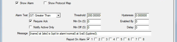
obj 1,alarm=GT/100.0
Sets alarm where alarm tag gives type and threshold. Alarm type codes are as follows:
GT= greater than
GE=greater than or equal
LT=less than
LE=less than or equal
*EQ=equal
*NE=not equal.
DV=deviates from threshold by hysteresis amount
CB=changes by
NO=none (used in CSV files)
Test type GT means the alarm is active if the object value is Greater Than the threshold given. Other comparisons are similar. DV amounts to testing for greater than or less than, but by the margin given as the threshold. CB means changed by the threshold amount since the last report or since start-up.
* Only the EQ and NE tests are valid for BIT/Boolean object types.
Note: The CB (changed by) alarm captures the first value of the object, and then notifies users if the value has changed by the threshold given. The new value that will be used to evaluate future changes is captured when the present alarm condition is acknowledged. For this reason, CB should only be used with requireack=yes. Ack is what resets the marker for the next change detection. Upon Ack, an alarm inactive message will be sent. Definition of active/inactive is a bit different for CB. Alarm “active” simply means change detected, and “inactive” simply means change acknowledged.
obj 1,sendto=1+2+4
Indicates one or more user group numbers 1 through 8 to send the alarm message to. Note that for groups, 1+2 means literally the string "1+2", not 3. Sendto=1+2 will give you groups 1 and 2, while 3 will give you group 3.
obj 1,minon=10
Sets minimum on time for alarm in seconds. The alarm condition must exist for this amount of time before it will become an active alarm. If the condition goes away before this time expires, the alarm is never reported.
obj 1,minoff=0
Sets minimum off time for alarm in seconds. The alarm condition must be clear for this amount of time before it will become an inactive alarm. If the condition goes away but returns again before this time expires, the alarm will simply remain in the previously reported active state.
obj 1,hyst=5.0
Sets hysteresis value applied to alarm thresholds. If alarm=GT,100 and hyst=5, then the alarm becomes active when the object value reaches 100, and the object value must fall below 95 before the alarm will return to inactive. This is intended to prevent nuisance alarms when the value is dithering right around the alarm threshold. (Does not apply to BIT/Boolean objects.)
obj 1,enableby=2/30
Selects another object that will enable this alarm. The alarm will be enabled with the given enableby object is nonzero. In this example alarms will not be produced by object 1 unless object 2 contains a nonzero value. The second value is a delay time in seconds. If non-zero, the enable will take effect this amount of time after the given object becomes non-zero. The delay applies to enable only. Disable will become effective immediately upon the object returning to zero if an object was given.
obj 1,requireack=yes
obj 1,requireack=no (default)
Selects whether the alarm must be acknowledged by an SMS reply. If the alarm notification requiring acknowledgement contained the identifier [1/14], then the acknowledgment reply would be:
Ack 1/14
Reply should be sent to the number that sent the notification. Sending “Ack” without any object number or sequence number will have no effect, and alarm notification may be repeated.
obj 1,activeonly=yes
Eliminates the alarm inactive notification when “yes”. Only the alarm active notifications will be sent. This enables the creation of enumerated notifications using multiple linked objects and EQ test type.
obj 1,message=”Send this message when alarm makes transition”
Sets the message that will be sent upon alarm transition. The message is sent once when the alarm first goes active, and a second time when the alarm goes inactive. The message must be a quoted string.
Several variables may be embedded within the message. These variables will be replaced with real time data at the time the message is sent. The {} brackets denote a variable, and the brackets and variable name within the brackets will be replaced. If resulting message won’t fit in 120 characters, make last 3 “…” to indicate that. Note: These variable names must be lower case.
| {site} | Inserts site name. |
| {name} | Inserts object name |
| {obj} | Inserts object number |
| {val} | Inserts object present value (formatted according to object type, integer, floating point, etc) |
| {lim} | Inserts threshold (limit) |
| {hyst} | Inserts hysteresis (useful in reporting DV alarms) |
| {test} | Inserts test type ("GT" for greater than, etc) |
| {%nnn} | Inserts a percentage value where nnn is a number that present value is divided by to give percentage (can result in “Tank is 12% full” type messages) |
| {opt\active\inactive} | Inserts first string if alarm is active and second string if alarm is inactive (see below) |
| {uptime} | Inserts system uptime in seconds (time since bootup) |
{opt\active\inactive} is a special case. If the alarm is active, then the active string will be inserted into the message. If the alarm is inactive, then the inactive string will be inserted into the message. For example, if the object included
obj 1, name=Fuel tank, message=”{name} level is {opt\ high\ normal}”
Then an active alarm would produce the message
[1/14] Fuel tank level is high
and upon alarm returning to inactive, would produce the message
Fuel tank level is normal
Note that the “opt” message can be more than one word. Everything between the delimiters \ and } are included in the string.
Note that two numbers are included at the start of every notification if acknowledgement is required. The first is the object number, and the second is the alarm sequence number. Each object has its own alarm sequence number that counts up from 1 and rolls over at 255. The alarm sequence number increments every time that alarm reoccurs. If the alarm requires acknowledgement, then the SMS reply must include those two numbers. (See requireack configuration parameter, and ack query.)
There is a Protocol tab or page in the configuration tool, but there is also a Protocol Map section for each object. The Protocol page is necessary for setting protocol specific parameters that apply to the entire VP3-TM device. The Protocol page settings are required for all applications. The Protocol Map section of each data object is required any time the VP3-TM will be configured to poll other devices to obtain data. If other devices will be writing data to the VP3-TM, then the Protocol Map section is left blank or unconfigured.
When the VP3-TM will be configured to poll other devices to obtain data, the Protocol Map section of the object configuration is how you tell the VP3-TM where to look.
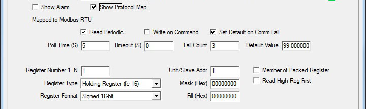
The Protocol Map section will show Modbus RTU parameters for a model VP3-TM10.
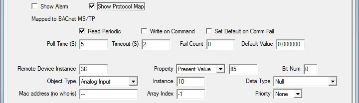
The Protocol Map section will show BACnet parameters for a model VP3-TM30.
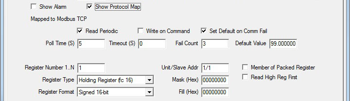
The Protocol Map section will show Modbus TCP parameters for a model VP3-TM60. The only difference between Modbus RTU and Modbus TCP parameters is that RTU will have a single number (see modslave parameter), the slave address, for Unit/Slave Addr, while Modbus TCP will have two numbers, device/unit, in the Unit/Slave Addr window (see modtcp parameter).
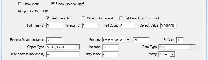
The Protocol Map section will show BACnet parameters for a model VP3-TM70. There are no configuration differences at the object level between BACnet IP and BACnet MS/TP.
Configuration parameters common to all protocol types:
obj 1,poll=5
Sets poll timer for reading. Setting is in seconds. Set poll=0 to disable periodic reading.
obj 1,writecommand=yes
obj 1,writecommand=no
Selects whether write on command is enabled for this object. Writing to a Modbus or BACnet device will only occur upon SMS command, only when received from a qualified SMS number, and only if the command is properly formatted. Unlike Control Solutions network gateways and other iReport devices, this device will never automatically write to an external device. The example command message
obj 1,value=50
would set object 1 to a value of 50 and write to the external device if enabled for writing. SMS has no direct access to the external device.
obj 1,defaultonfail=99.99/3
Tells the communication engine to set the object to a default value upon some number of communication failures. Syntax is defaultonfail=<value>/<count> where <value> is the default value to be set upon <count> failures. The fail count applies when operating as Modbus master or BACnet client. If the master/client query failed this number of times, then the object is set to the default value. When operating as slave/server, and a timeout is given, the object will be set to the default value if the remote master/client has not updated the object within the timeout period. When operating as slave/server, the default value is used, but count is not used. Count would simply increase the timeout by some multiple. If a longer timeout is desired before the object should assume its default value as slave/server, then simply change the timeout parameter. Use defaultonfail=0/0 to disable setting the object to any default (configuration defaults to disabled).
obj 1,timeout=0.5
Sets timeout, in seconds with resolution to tenths. When operating as Modbus master or BACnet client, this timeout results in a “no response” error if the remote slave/server did not respond in time, and optionally results in setting the object to the default value if “defaultonfail” is set. When operating as Modbus slave or BACnet server, results in optionally setting object to default value if remote master/client did not update this object within timeout period provided “defaultonfail” is set.
Note: If multiple registers become grouped into a single Modbus request, the timeout specified for the first object in the grouping will become the timeout for the entire request, meaning the timeout is implied to be the same for all objects in the group. Setting the object timeout to zero will result in the global default timeout set for the device to be used instead, and this is acceptable and recommended as a short cut if all timeouts will normally be the same.
Note: Timeout setting in Modbus only applies to RTU master or slave, and TCP slave. Timeout for Modbus TCP master/client is fixed at 10 seconds.
Use of timeout when VP3-TMxx is slave or server: The timeout will be reset when the object is written. If the object is not rewritten within this timeout, then a “no response” fault will be indicated, and if defaultonfail is set, the default value will take effect. Note that a default fail count other than one does not make sense when using defaultonfail for a slave/server. The timeout applies only to writing the object, and will go into effect upon the first write to this object. Reading the object will not set or reset the timer. This timeout is intended to make sure a remote master or host continues to periodically update the VP3-TMxx with new values. Set it to zero to disable the timeout if not used. Note: If the write times out but reads continue, the “comm fail” message will be sent, but the “device offline” message will not be sent.
Configuration parameters for Modbus models:
obj 1,modreg=201
Sets remote Modbus register number, indexed from 1, not Modicon.
obj 1,modaddr=200
Sets remote Modbus register address, indexed from 0. This is an alternate form of modreg, and only one or the other should be used as modaddr will overwrite modreg and vice versa. (Note: Only register numbers starting at 1 are used in the configuration tool.)
obj 1,modtype=4X
Set Modbus register type – determines Modbus function code. Types are:
NO=none
0X=coil (read/write)
1X=discrete input (read only)
3X=input register, 16-bit (read only)
4X=holding register, 16-bit (read/write)
0XS=single coil
4XS=single holding register
The single (S) designation applies only when writing, and selects function codes 5/6 instead of 15/16 (default for 0X and 4X). The function code for read is the same either way.
obj 1,moddata=UINT16
Sets Modbus remote register data format.
NONE=undefined
INT16=signed integer, 16-bit
UINT16=unsigned integer, 16-bit
INT32=signed integer, 32-bit
UINT32=unsigned integer, 32-bit
INT64=signed integer, 64-bit
FLOAT=floating point, IEEE 754, 32-bit
BIT=Boolean, single bit, applies to coil or discrete input ONLY
MOD10-2=Schneider Electric Mod10 format, 2-register
MOD10-3=Schneider Electric Mod10 format, 3-register
MOD10-4=Schneider Electric Mod10 format, 4-register
obj 1,modmask=0080
Sets data mask in Modbus map for Modbus bit masking. This object will take on the value of the remote Modbus data logically AND-ed with this mask, and then right shifted so that the least significant bit of interest becomes the LSB of data.
IMPORTANT: Bit mask in Modbus map will only be recognized if pack=”1” is also used, even if the masking applies to only a single register. Mask value may be 16-bit or 32-bit.
obj 1,modfill=0080
Sets data fill for use in writing packed registers, has no effect on reading.
Note: Consecutive Modbus write maps may be “packed”. If any of the included objects is commanded for write, then all included objects are accumulated for the write to the external device. If only a single bit should be commanded within a packed register, then all of the bits should be read by one or more objects, with the desired object enabled for writing.
obj 1,modslave=5
Sets Modbus RTU slave address to be read/written for this map.
obj 1,modtcp=1/5
Selects the TCP device from device table, and provides TCP unit number instead of RTU slave. Syntax is tcp=<device>/<unit>. Used only in TCP version of device. Both RTU and TCP are simultaneously active in the TCP device.
obj 1,modbigend=yes (or no, default=no)
Sets Modbus register swap flag for this object map. Only applies to multiple-register data values, such as Int32 or Float. If “yes” for big endian, this means the Modbus slave contains the high order data in the first or lowest numbered register. If “no” (default), then the low order data is in the first or lower numbered register.
obj 1,modpack=yes (or no, default=no)
Set this option flag if the same register will be shared among multiple objects using bit masking. Even if a single register is to use a bit mask, this flag must still be set to cause the mask to be recognized.
IMPORTANT: To be sure all components of a packed register do get included, make sure the first object included in the register has the desired poll time while all other objects associated with the same register have a longer poll time. All timeouts are reset when the packed register is processed. By forcing the first component to always time out first, all components will always be included. If a component further down the list has a shorter poll time, all components prior to that will be skipped in the assembly of the packed register.
Configuration parameters for BACnet models:
obj 1,bacdesc=”Send this message when alarm makes transition”
The SMS message is accessed via BACnet as the object’s description property. The command obj 1,bacdesc="xxx" is the same as obj 1,message="xxx". The message is accessible as BACnet object description for purposes of making it accessible to BACnet queries.
obj 1,bacunits=95
Specifies BACnet Units property for this object. (Note: Name selected in configuration tool drop down list for units is translated into the appropriate BACnet protocol code when sent to the VP3-TM.)
obj 1,bacdev=10
Sets remote device instance for BACnet client mapping. This is the device instance that the VP3-TMxx will look for using Who-Is, and subsequently send the configured BACnet read/write property request.
obj 1,bacobj=AI/1
Selects object type and instance which the BACnet client is to read/write at remote device instance. The following object types are supported by the client:
AI=Analog Input
AO=Analog Output
AV=Analog Value
BI=Binary Input
BO=Binary Output
BV=Binary Value
MI=Multi-state Input
MO=Multi-state Output
MV=Multi-state Value
DEV=Device
obj 1,bacmac=3 (hexadecimal)
obj 1,bacmac=c0:a8:0:2:0b:ac (indicates IP address 192.168.0.2 port 47808)
If specified, this MAC address will be used by the BACnet client to attempt to reach the remote BACnet device when Who-Is fails. This is used for devices that do not support Who-Is. A MAC address of 1 byte will imply MS/TP while a MAC address of 6 bytes will imply IP (if supported by hardware).
obj 1,bacprop=85
Selects object property to be read/written at remote device.
obj 1,bacdata=BIT
Specifies data encoding to be used when writing remote device. Supported data encoding types are:
NULL=BACnet Application Tag Null (0)
BOOL=BACnet Application Tag Boolean (1)
UINT=BACnet Application Tag Unsigned Int (2)
SINT=BACnet Application Tag Signed Int (3)
REAL=BACnet Application Tag Real (4)
BIT=BACnet Application Tag BitString (8)
ENUM=BACnet Application Tag Enumerated (9)
obj 1,bacpriority=10
Specifies the command priority that should be used when writing a commandable object in the remote device.Commandable objects are any Output object. Commandable Value objects are not supported.
obj 1,bacindex=2
Specifies an index value if reading/writing an array, or “no index” if -1. Defaults to “no index”.
obj 1,bacbitnum=1
Specifies a bit number to read a single bit from a bit string. The VP3-TMxx will not read an entire bit string as a single cumulative value (cannot make a meaningful alarm for that) but it will read an entire bit string and save a selected bit position from that string (value of 0 or 1). The bacbitnum is used to specify bit positions starting at zero. Bit strings cannot be written by the VP3-TMxx.
Copyright © 2019 Control Solutions Minnesota, Inc.