
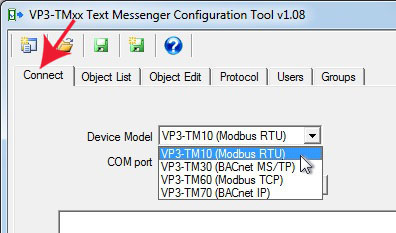
Selecting your i.Report model from the Device Model list is only necessary when you are working with configuration off-line, i.e. not actually connected to the VP3-TM. When you connect to a device, the model will be automatically selected for you.
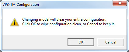
When you select a different model from the Device Model list, you will be prompted to continue. Changing model clears configuration in tool memory. The device, if any is connected, will not be affected. The device model change only clears configuration tool memory (to avoid trying to re-cast Modbus parameters as BACnet for example).
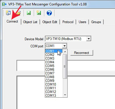
You will need an RS485 connection between the NET terminals on the VP3-TM, and your PC/laptop. Most often, you will be using a USB to RS485 adapter. Follow the installation instructions for that adapter as applicable. From your PC’s device manager, find out what COM port it was installed as, and select that port on the Connect page. If you are using a RS232 to RS485 adapter on an older style COM port on the PC, select that COM port number from the list, usually COM1.
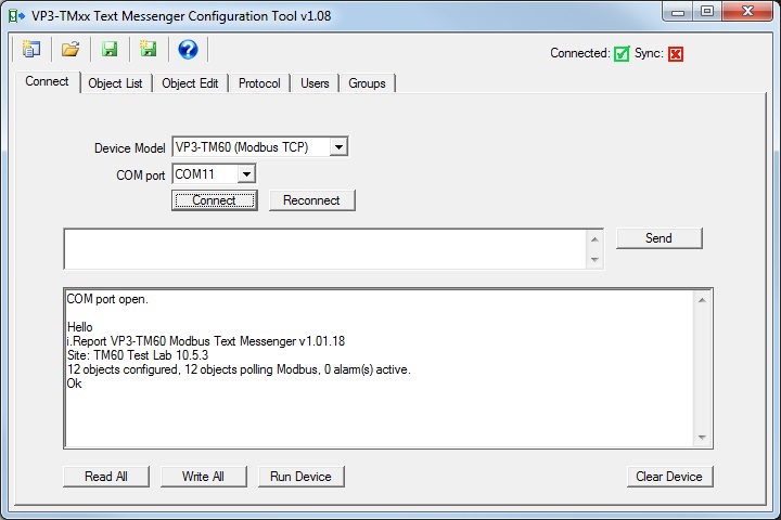
The Connect and power-up sequence is important. Select your COM port from the list, and then click the Connect button. After clicking the Connect button, apply power to the VP3-TM. The configuration tool will wait about a minute to see the startup “Hello” from the VP3-TM. The tool will then send the “show” command to the VP3-TM, which results in displaying the summary information as illustrated above.
Here is why timing is important: If the VP3-TM does not see a command from the tool console within 10 seconds after power-up, it will automatically exit configuration mode and attempt to begin normal operation. Once it begins normal operation, you will be unable to configure it. Therefore, clicking the Connect button and then applying power will let the tool send the “show” command immediately upon seeing the startup “Hello”, and you have now “locked” the VP3-TM in configuration mode.
The fact that you are in configuration mode will be indicated by the LED labeled “STA” remaining on solid amber. In normal operation, this LED will be off, or flashing. If on solid amber, you are in configuration mode.
If you have disconnected and reconnected your serial port for any reason, and want to reconnect to a VP3-TM that is already in configuration mode as indicated by the STA LED, click the Reconnect button instead of Connect. The Connect button will wait to see “Hello”, while the Reconnect button will simply go ahead and send “show”.
When you are done configuring your i.Report and want to proceed with normal operation, click the Run Device button. This will cause the VP3-TM to exit configuration mode and start running as configured.
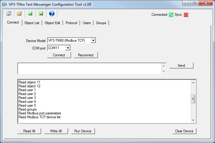
While you are in configuration mode, you can read and write various individual parameters from other tabs or pages in the tool. But if you want to read or write everything known to the VP3-TM, click the Read All or Write All buttons.
If you want to retrieve the entire configuration from a VP3-TM that has been previously configured, click Read All. However, what is read will simply be “added” to whatever is already stored within the tool’s tables. Therefore, to get a clean representation of only what is in the device, click the “New” icon (very top left corner) first. This will clear everything from the tool’s memory. Now proceed with the Read All.
If you want to send every bit of configuration currently in the tools memory to the connected VP3-TM device, click Write All. However, what is written will simply be “added” to whatever is already in the device’s memory. This will be suitable for modifying an existing configuration, but if any part of the configuration being sent is intended to replace existing configuration, you should start by first clearing the device. Click the Clear Device to completely erase all configuration currently stored in the VP3-TM device. Wait several seconds for this process to complete - a message will be displayed indicating completion. Now proceed with the Write All.
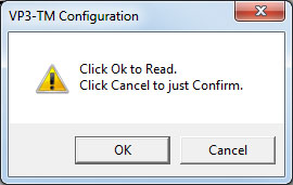
When you click Read All, or any Read Device button anywhere else in the configuration tool, you will be prompted to Read or Confirm. If you click Ok on this dialog, the tool will proceed to read configuration from the connected device and save everything it finds in the configuration tool memory as noted above. However, if you click Cancel indicating you want to just Confirm, then the tool will read configuration from the device but only compare what it finds to what it already had in configuration tool memory. If the configuration does not match, the "in sync" icons will turn to a red X where applicable.
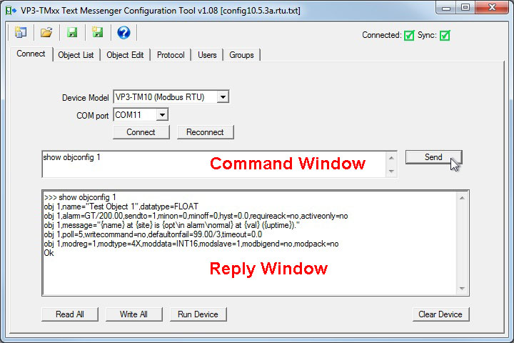
The Connect page doubles as a command console while in configuration mode. You can type any command into the command window, click Send, and wait for the response in the reply window. Any of the commands documented throughout this user guide can be entered here.
There is really no magic going on behind the scenes of the various tabs or pages in the configuration tool. It simply provides templates for creating the configuration script you see displayed when you enter a command like “show objconfig 1”. You could turn around and type any of this right back into the command window and reconfigure the object right here. You actually don’t even need the configuration tool software. Any generic serial terminal emulator such as PuTTY or HyperTerminal could be used to type the same commands and configure or query the connected VP3-TM.
If you wish to use a generic terminal emulator, connect to the NET terminals of the VP3-TM using an RS485 adapter, and open the COM port at 19200 baud, N81. Then simply type "show" (and return) as soon as you see "Hello" upon power-up. You will now be in configuration mode.
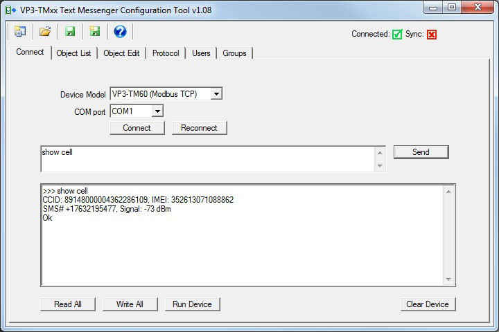
Type “show cell” in the command window and click Send. Provided the VP3-TM has been up long enough for the cellular modem to connect to the network, the response to the “show cell” command will be a display of the CCID (SIM card number), IMEI (cellular device identifier), phone number assigned by the carrier, and signal strength. Signal strength will be indicated as a number in the range of -51 dBm to -113 dBm with -51 being a perfect signal and -113 being call-dropping bad.
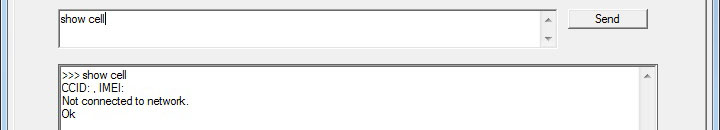
If you send the “show cell” command right after power-up, you will get no CCID indication because the modem is still in the process of waking up. It takes typically 30 to 45 seconds before you will see the CCID indication.
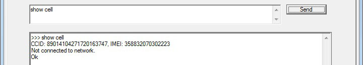
The CCID and IMEI numbers will be displayed even if the modem has not managed to connect to the network yet. Under normal conditions, the modem will connect within 1 to 2 minutes after power-up. If the VP3-TM has been off for a long time, the initial network connection sometimes takes a bit longer. If the antenna is disconnected or you have a poor signal for some other reason, including location or being inside a metal building, it might never connect. Of course the other potential reason for not connecting is that your SIM is not active.
 |
Referred to as the “New” icon, click this to clear configuration stored within the tool. |
 |
Open a configuration file and load it into the configuration tool. From the Connect page, this opens and loads a configuration script (text) file. From the Object List page, it imports a CSV list of objects. From the Users page, it imports a CSV list of users into the phone book. |
 |
Saves configuration to a file already opened for reading or writing. |
 |
Saves (creates) a new configuration file, writing all configuration currently saved within the tool memory into the new file. |
 |
Saves a CSV file already opened for reading or writing. |
 |
Saves (creates) a new CSV file with content relevant to the page where used. This will create a CSV list of objects from the Object List page, or a CSV list of users from the Users page. |
 |
Used to access the user guide from within the configuration tool. |
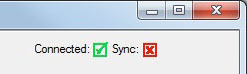
The Connected icon will be red if the tool is not connected to a VP3-TM, and green if it is connected via the serial port.
The Sync icon will be red any time configuration changes made in the tool are not in sync with configuration in the device. The Sync icon will become green after Read All or Write All. If changes are made to an individual object, the Sync icon will become red, but will return to green when that one object is written to the VP3-TM by clicking Write Device from the Object Edit page. The same practice applies to users, groups, and protocol settings.
Copyright © 2019 Control Solutions Minnesota, Inc.