
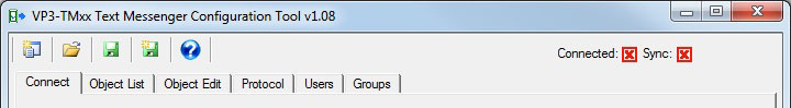
The VP3-TM configuration tool is free software you may run on any Windows PC. It streamlines the process of configuring the VP3-TM. When you open the tool, you will see a tabbed set of pages that are organized mostly in order of how you will typically use them. In this section, we will run through a quick overview of setting up the VP3-TM for the first time.
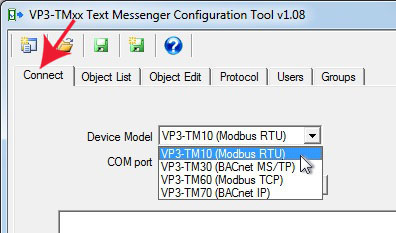
We are going to start by creating a simple configuration with a single alarm, and create that configuration “off-line” before connecting to the VP3-TM. To do this, start by selecting your VP3-TM model number from the device model list on the Connect page.
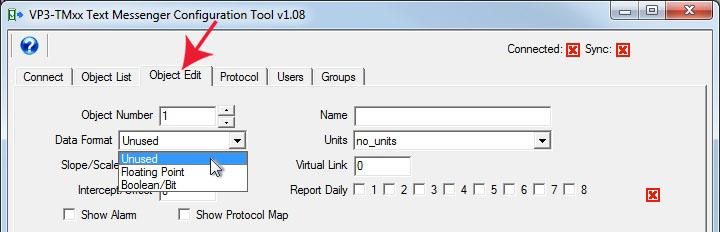
Next, go to the Object Edit page. The VP3-TM has data “objects” that it maintains internally. The data value held by the object is compared against the alarm threshold to determine if there is an alarm. The data value was obtained by the VP3-TM reading it from another device on the network, or by some other device on the network writing to the VP3-TM. The data can be floating point or Boolean (on/off), or in the case of Modbus can also be integer.
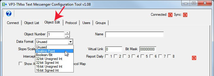
The first step in configuring a data object is to select a data format that best matches what you anticipate the source of data to be. An exact match is not an absolute requirement since data will be automatically converted as necessary by the VP3-TM. But if you know the only options are on and off, then floating point level does not make a lot of sense as a way of representing that. Conversely, a single bit (Boolean) is not going to be capable of representing a temperature reading.
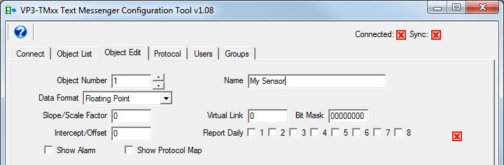
The other thing you will want to do for each data object is give them a unique name. Beyond that, all other parameters are optional. If scale factor is left at zero, that will be interpreted as “none” and be mathematically treated as 1.
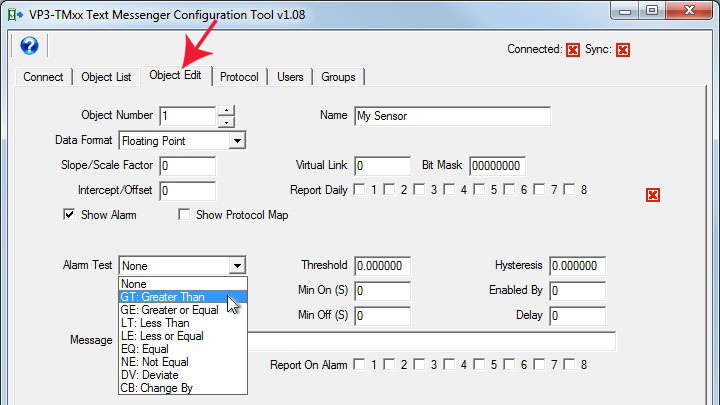
It is possible to configure an object with no alarm just to get a daily report of its value. But alarm monitoring generally isn’t going to be useful without defining an alarm. Start by checking the box marked “Show Alarm” to make the alarm settings visible.
The first step in defining an alarm is to select an alarm test, such as “greater than”. If the test is “greater than”, then the alarm will be considered active any time the present value of the object is greater than the threshold value. (Refer to section 7.2 for further details on all of the alarm test types.)
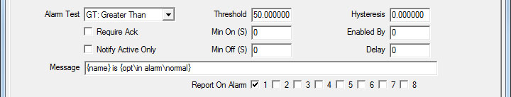
There are three additional settings beyond alarm test that need to be entered in order to make the alarm useful: (1) Enter a value for the threshold. (2) Enter a text string for alarm message. (3) Select at least one user group to report to. The check boxes after “Report On Alarm” represent the user groups that the message should be sent to. Message content is further discussed in section 7.3 of this user guide.
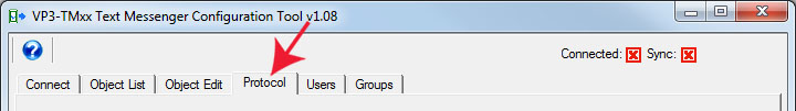
The VP3-TM will be communicating with one or more other devices to monitor those devices. This will require protocol settings that will vary by protocol, and in turn vary by VP3-TM model number. Refer to the applicable protocol settings discussed later in this user guide. We are at this point only calling your attention to the fact that something here will most likely need to be set.
The one setting on the Protocol page that does not vary is the Site Name. Be sure to give your VP3-TM a site name as this will often be used in generating messages.
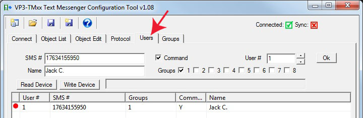
The alarm messages will not go anywhere until you enter at least one user - most importantly that user’s mobile phone number - in the phone book. The user’s name does not get used anywhere other than to be displayed in the configuration tool. What matters is the phone number, and selecting at least one user group for that user to be a member of.
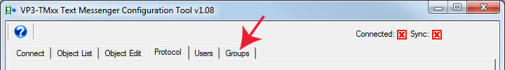
The groups tab is where you configure the user groups. Assigning users to group #1 and not configuring anything on the groups page will work just fine. All groups are always active. The only thing configured on the groups page is additional qualifiers for each group. With no qualifiers set and both delay and repeat times left at zero, users in the group will receive all normal alarm notifications immediately. The only thing not received with no qualifiers set will be error and failure messages, and admin messages. Error messages are not user configurable - you only have the choice of whether to receive them or who is to receive them.
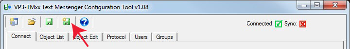
Now that you have your initial configuration set up, you should save it. Go back to the Connect page and click the new file icon. You will be prompted with the usual Windows dialog to provide a file name to save.
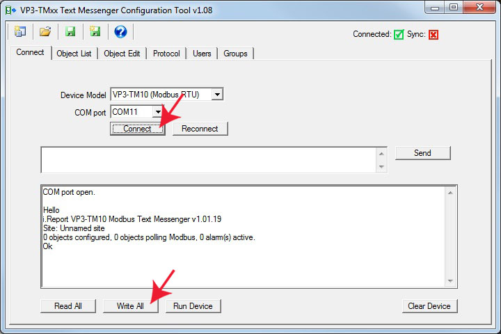
At this point, you should be ready to send your configuration to the VP3-TM. You will want to connect by selecting the applicable COM port and then clicking Connect, after which you should power up the VP3-TM that is connected via an RS485 adapter.
Once you see the initial Hello message, you can click Write All to send your entire configuration to the VP3-TM. If this is not the first time you have sent any configuration to the VP3-TM, the Hello message will indicate that objects are configured. In this case, you should click the Clear Device button first, and wait a few seconds for it to indicate it is finished. Then proceed with Write All.
Once the configuration has been written, click Run Device to exit configuration mode, close the tool software, disconnect the RS485 adapter, and connect the VP3-TM to the device(s) it should be monitoring.
Copyright © 2019 Control Solutions Minnesota, Inc.