
|
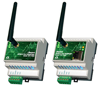
The i.Report Text Messenger is a self-contained remote monitoring and alarm notification system that monitors data points in one or more Modbus/BACnet devices and alerts you and others via SMS when an event has been detected that somebody should know about. The i.Report Text Messenger offers simple yet powerful remote monitoring without the need for a monitoring service - no contract required. You decide what events somebody should know about, and who should know about them. If the event is important, you can require the alarm message recipient to acknowledge the notification. You also have the option of escalating the notification to additional users if the first user (or group of users) did not respond by acknowledging the alarm within the time limit you set. A single i.Report can monitor up to 100 data points from a single device or from multiple devices on the network. An event can be a level exceeding a threshold high or low, a change in state, change in value, or deviation from a setpoint. The parameters that decide what constitutes an active alarm are set up with an easy to use template. A notification is sent when the alarm transitions to "active", and again when the alarm transitions to "inactive". If acknowledgement is required but not received within the time you allowed, the active alarm notification is repeated, possibly including additional users each time if you set it up that way. The notification message consists of whatever text you provided, optionally including template variables. These "variables" are replaced with dynamic data, such as present level, at the time the message is sent to users' mobile phones. The i.Report Modbus Text Messenger can be Modbus master or slave. As master, it will poll other Modbus slaves, querying the registers you have selected and evaluating register content against alarm criteria. As slave, you can have your PLC or SCADA system write data to the i.Report for alarm evaluation. As a slave, the i.Report will contain up to 100 holding registers addressable by your PLC or SCADA. Modbus RTU also includes "Sniffer Mode" which means you can monitor Modbus data without any reprogramming of the Modbus devices being monitored. As long as there is traffic on the network between a master and one or more slaves, you can monitor it and receive notifications when your selected registers match the criteria you set. Modbus TCP does not need sniffer mode because you can always have multiple masters on a TCP network. So if you know what register you want to look at, just poll it. The i.Report is also useful for "non-network" monitoring applications. There are many industrial sensors available with Modbus capability. For mobile applications, a Modbus GPS receiver is available, and a simple geo-fencing implementation can be configured. Control Solutions offers three different models of ValuPoint Programmable I/O which may be used to interface multiple sensors, and even remotely controllable actuators. The i.Report BACnet Text Messenger can be a BACnet client or server. As a client, it will read properties from objects in other BACnet devices and retain copies of that data for evaluation against alarm criteria. As a server, the i.Report will contain a collection of Analog Value and/or Binary Value objects which other BACnet devices may write data to. Data written to these objects by other BACnet devices will be evaluated against alarm criteria for possible notification. The i.Report BACnet Text Messenger can be used in multiple ways in Building Automation Systems. You can provide alarm monitoring and notification regarding specific equipment such as chillers, compressors, pumps, air handlers, etc., and do this monitoring without reprogramming anything. Because the i.Report represents no network security risk, you can implement monitoring without impacting IT management. This makes i.Report a useful diagnostic tool that can be quickly added without impacting existing BAS programming. The i.Report BACnet Text Messenger can also be an alternate method of generating SMS notifications at the direction of the BAS front end system. The i.Report sends SMS messages directly to the cellular network without the need for passing messages through an external SMS gateway. |
|
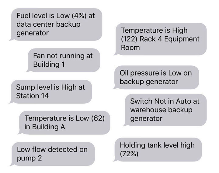
The notification message can say almost anything you can dream up. The notification can be triggered by exceeding a threshold high or low, a change in state or value, or deviation from a setpoint.
The message can be anything you like. To make the messages more meaningful, there is a set of variable names that can be used to get real time information when the message is created. For example, if you include “{val}” in your message, the {val} will be replaced by the actual value of that data point as of when the message is created. Other variables include {site} for site name or location of the VP3-TM or {name} for name of this particular data object. Refer to the section about alarm message formatting later in this user guide for the complete list of available variables.
One of the more interesting variables is {opt\a\b}. This means text option. If the alarm is active, then text string “a” is included in the message, otherwise text string “b” is included. An example using “opt” would be "{name} at {site} is {opt\too high\normal}”. If the object name is “Tank level” and site name is “Station 1”, then the message delivered when the alarm is active would be “Tank level at Station 1 is too high.”
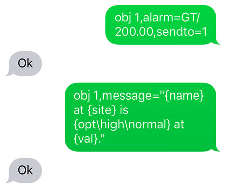
You can do everything needed to configure the VP3-TM entirely via SMS. This is most useful for making changes after the remote monitoring is already deployed at some remote location. You will find initial setup is greatly streamlined with the use of the free configuration tool software provided by Control Solutions.
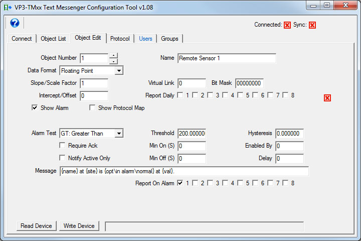
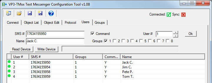
The VP3-TM configuration tool provides easy templates to fill in for configuring data points and their respective alarms, as well as entering users in the phone book. To further speed up the process, you can create a list of data points using a standard spread sheet program (e.g. Excel). Save your data points as a CSV file, and the VP3-TM configuration tool will import your entire list at once. A CSV import may also be used to import your list of users into the phone book.
Once you have created the initial configuration, you can save your entire configuration to a text file as a configuration script. Your data points, alarm settings and messages, and phone book are all included in this file. This is useful both as a backup copy, and for duplicating the same configuration for a second similar site.
The phone book holds up to 50 users. Each user should be included in one of the user groups, and may be included in more than one. There are 8 user groups available. When an alarm notification is sent, it is sent to a user group. All of the users included in that group will be sent the same message at the same time.
User grouping allows certain messages to be sent to one group of users while other messages are sent to other users if desired. Each group also has an optional delay and repeat time. The combination of delay, repeat, and group selection is used to create an alarm escalation scheme whereby if the group initially notified does not acknowledge the alarm within the time limit you provide, then the next group will be notified.
User groups are also assigned attributes determining whether that group receives messages about communication errors and failures, and administrative messages. The admin user will receive messages pertaining to other users. For example, the “admin” user(s) will receive a notification if some other user has replied “stop” to stop receiving messages.
Start by creating your configuration. Create some data points and give them some alarm parameters. Create the message that should be sent. Add a user or two to the phone book.
Save all of this to a configuration file, and do this from the Connect page in the configuration tool.
Next, get connected to the VP3-TM. You will need an RS485 connection between the NET terminals on the VP3-TM, and your PC/laptop. Follow directions in the “Getting Connected” section of this user guide.
Once connected and communicating in “configuration mode”, write your configuration to the VP3-TM.
While still in configuration mode, follow instructions as applicable for activating the SIM in your VP3-TM. If using the pre-installed SIM provided by Control Solutions, instructions for activation are found in Appendix A of this user guide. Verify SIM activation as noted under “Getting Connected”.
You have the option of sending a test SMS message to yourself via the VP3-TM at this point. You also have the option of testing your alarms before connecting the VP3-TM to whatever it will actually be monitoring. Both of these topics are covered in the section titled “Diagnostics and Trouble Shooting”.
Finally, connect the VP3-TM to the device(s) it is intended to monitor. Since every application is different, we can’t tell you exactly how to verify your device is being monitored, but typically there will be some data points you can look at and come to a satisfactory conclusion. Some suggested diagnostic SMS queries may be found in the section titled “Diagnostics and Trouble Shooting”.
• Self-contained remote monitoring and alarm notification system
• Monitors data points in one or more Modbus/BACnet devices
• Alerts one or more users via SMS when an event has been detected
• User configurable SMS messages with dynamic content templating
• Up to 100 data objects (Modbus registers or BACnet objects)
• Alarm settings and SMS message content programmable per object
• Up to 50 user phone book, 8 user groups
• Notify multiple users with configurable delay and repeat times per group
• Notification escalation with repeat when not acknowledged (optionally configured)
• Password protected replies accepted from known authorized users
• Unrecognized phone numbers ignored
• Optionally change parameters or command outputs remotely via SMS
• Modbus TCP 10/100BaseT, Modbus RTU 1200 to 38400 baud
• BACnet IP 10/100BaseT, BACnet MS/TP 9600, 19200, 38400, 76800 baud
• Master or slave, client and server
• Up to 20 Modbus TCP devices, up to 100 Modbus RTU devices
• Compatible with AT&T or Verizon 4G LTE
• Operating voltage: 10-30VDC, 24VAC
• Operating current: 0.1A @ 24VDC typical, 0.4A @ 24VDC peak (transmitting, 500mSec duration typical)
• Temperature: -40 to +85°C (SIM card excluded), 95% relative humidity non-condensing
• Mechanical: DIN rail mount, 100mm H x 70mm W x 60mm D
Copyright © 2019 Control Solutions Minnesota, Inc.