
You can send a test SMS message from the command console to any mobile phone number. The number does not have to be in the Users list (phonebook) to send a test message.
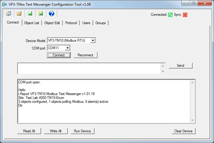
The first step is to get connected to the VP3-TM as discussed in Section 6.
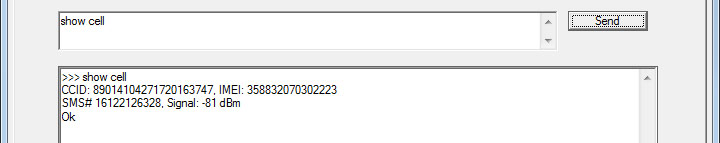
You cannot send a message until the cellular modem connects to the network. Verify the connection using the "show cell" command. If you are not yet connected, you will see "Not connected to network" instead of a signal strength indication.
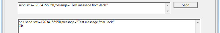
Now use the send command to send a test message as illustrated here. Note that the message must be enclosed in quotes.

The SMS message should show up on your cell phone within a reasonable amount of time. Usually it will be fairly prompt. Sometimes it may take several seconds, up to a minute or two depending on the cellular network.
Note that the LNK (link) LED on the VP3-TM will be on solid if the cellular modem is not connected to the network, and will normally be blinking at a rate of about twice a second if connected. If it begins to blink with a pattern of two flashes and then a pause, this is the indication that the last attempt to send an SMS message failed.
If the SMS send failed during normal operation while sending a notification to a user in the phone book, you will be able to check the error code using the "show usererrors" command. However, the send command here does not log error codes since the phonebook is bypassed in this test mode.
An obvious way of testing alarm notifications is to observe something happen in the field that should result in an alarm, and verify that you receive the notification on your mobile phone. But there is a way to "bench test" the alarms before ever placing the i.Report in the field.
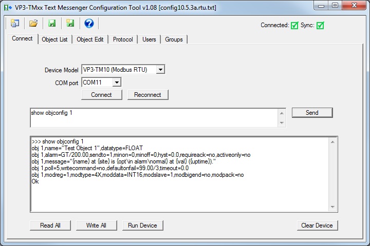
Start by connecting to the VP3-TM with the configuration tool. Make sure you are in configuration mode as confirmed by the STA LED remaining on solid amber. Verify that you have configured the point you are about to test using the "show objconfig" command. In this example, our object will normally be polling a Modbus register. For test purposes here, you will want to have the Modbus device disconnected. You can't poll Modbus and use the command console at the same time.
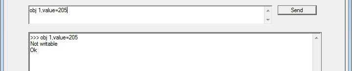
Use the value command to set the value of the object from the console. This sets the data value as if it had read that value from your Modbus device. In this case, we see an error message because the object was not configured as writable. It will not normally need to be writable in most cases, but for test purposes, we need to at least temporarily enable writing to the object.
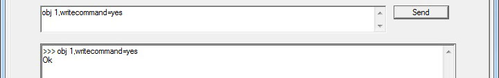
Enable writing with one minor configuration change. The other change you may want to do temporarily is get rid of the defaultonfail since this will result in setting the object value due to the fact that Modbus is disconnected.
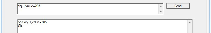
We can now successfully set the object value, and in this example, we are making sure we set the value above the alarm threshold.
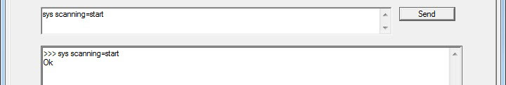
The other thing you must do to test alarms is enable scanning. Alarm scanning is normally disabled in configuration mode, and automatically enabled when you exit configuration mode. For purposes of testing alarms, you will need to enable scanning while still in configuration mode.
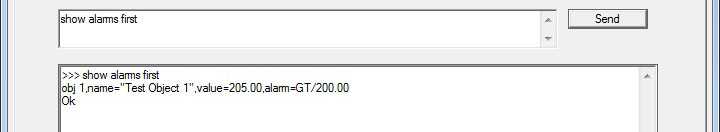
If you have followed the above sequence on your live VP3-TM device, and had previously configured your own mobile phone number in the Users list, you should receive a notification shortly after enabling scanning. You can also check alarms using the "show alarms" command at the console.
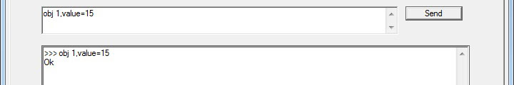
Now we set the object value back below the alarm threshold. If you received the alarm active notification, you should now receive the alarm inactive notification.
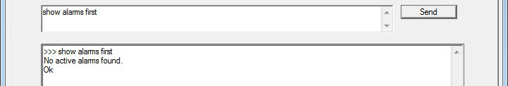
You can verify the alarm was cleared using the "show alarms" command.
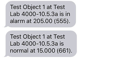
The text messages received on our cell phone while preparing this example are illustrated here.
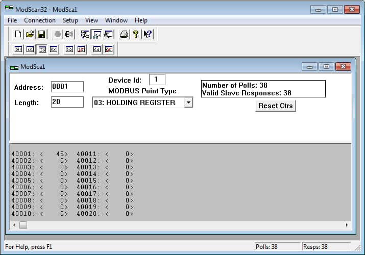
The Modbus diagnostic tools we use most often at Control Solutions are ModScan32 for testing Modbus slaves (either RTU or TCP), and ModSim32 for simulating Modbus slaves when testing Modbus masters. These are available for purchase (from Win-TECH) for a very reasonable price.
These are certainly not the only Modbus tools available for purchase (see note about searching for others below). Win-TECH is simply the one that has been around the longest, and we have been using their products for about 20 years. We find that if ModScan can talk to it, there is a 99.99% chance that anything else we make can talk to it as well. After further analysis, we found that those rare exceptions were with devices that did not fully comply with Modbus protocol specifications in the first place.
Win-TECH site for purchasing ModScan/ModSim: ModScan/ModSim
Simply Google "Modbus RTU test software" or "Modbus TCP test software" to find an assortment of Modbus test tools. Some are free, some have a free demo, and others are available for purchase. We at Control Solutions have tested some of these, and know that our customers have also tested others. We do not use all of the available tools on a regular basis, and are therefore avoiding any specific endorsements here.
No-response errors are probably the toughest because it means no activity is being recognized. CRC errors are marginal progress because it says the devices are at least seeing some bits on the line, even if the bits don’t make sense yet. Exception errors are a good sign because it means you are successfully communication with the Modbus device. Receiving an exception error requires receiving a good packet with a good CRC check. This means communication is ok, but configuration is asking for something the Modbus device does not like.
No-response errors:
• Check to see that communication parameters are correct (baud rate, etc).
• Check to see that the slave address matches.
• Check to see that Pre-Delay is at least 50 mS.
• Check wiring and power.
• Check for reversed polarity on RS485 lines. If uncertain, just try swapping them.
• Check to see that slave device is enabled for Modbus communication (many devices default to disabled)
CRC errors:
• Check baud rate and character format.
• Check wiring – if everything else is correct, CRC errors mean noise on the line.
• Check for reversed polarity on RS485 lines. Reversed polarity often looks like just noise.
• Check to see that Pre-Delay is at least 50 mS.
Exception errors:
• Check configuration. You cannot receive an exception error report if you are not successfully communicating with the Modbus device. Wiring, etc, is not a problem. Configuration has something wrong (most often the register number requested is not available).
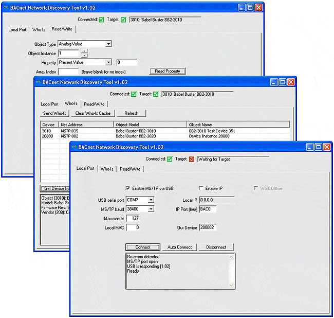
This free tool, when accompanied by the MTX002, can be used to help you locate MS/TP devices when you may have lost track of settings such as baud rate, max master, MAC address, etc. If you know what speed the network is running at, select the baud rate and click Connect. But if you need to “search” for the right baud rate and other settings, click Auto Connect and wait a minute or two. The discovered baud rate, along with discovered max master setting, will be displayed when the auto connect process is done.
You may also use this tool as an object browser. Once you have selected a device on the Who-Is tab, go to the Read/Write tab. The object types supported are included in the Object Type list - only the basic types are supported by this tool. The most common properties are listed in the Property drop down list, but you can select “Other” and enter the BACnet property code in the window next to the list. For example, 85 would give you present value.
This tool is useful without any additional connection hardware if using it with BACnet IP. Using it with MS/TP requires the Control Solutions MTX002 USB to MS/TP adapter. This tool will not run with a generic RS-485 port adapter. A standard PC serial port with an adapter is not capable of 76800 baud, but the MTX002 does allow your PC to connect to an MS/TP network running at 76800 baud.
Download the BACnet Network Discovery Tool under the Tools link at csimn.com.
An MS/TP device that is functioning normally will always be at least passing the token, and usually polling for master periodically. The only time a device will not poll for master is if another device exists on the network with a MAC address only 1 greater than the gateway itself. It then just passes the token to that device without any intermediate polling for master.
Two particular indications of the MS/TP token LED are worth noting.
If the token LED appears to be on nearly solid yellow (or amber), this means the gateway is doing nothing but poll for token, which implies it is not finding any other devices on the network. You will see this any time you apply power to the gateway without connecting any network. If the network is connected, there is a problem with connections or port settings.
If the token LED is completely off and never flashes on, this means the gateway is hearing other traffic on the network, but just not connecting. An MS/TP device is required to "be quiet until spoken to". Therefore, if there is chatter on the network, but the gateway cannot find anything that is addressed to the gateway, it will remain quiet. This problem is usually the result of problems with port settings.
An MS/TP device can alternate between the above two conditions. The "be quiet until spoken to" rule is up for grabs when the entire network is powered up simultaneously. Whoever wakes up first will be generating all the chatter while everybody else on the network listens.
If the token LED is very intermittent, flashes rapidly a few times (including green on the token LED), then is off completely for a period of time, this usually means it is trying to talk, thought it was talking or actually was for a bit, but something got out of sync. If there are duplicate device addresses on the network or mismatching Max Master settings, this will result in the appearance of intermittent communications.
Check your wiring. Noise on the line resulting from not following RS-485 wiring guidelines will result in communication problems ranging from no connection at all to frequent errors. Also be sure that you have a ground connection between all devices on the network. The RS-485 network is not a 2-wire network. You need two data lines plus signal ground. If you consider cable shield a connection, then you need 4 connections.
The VP3-TM was designed to notify you when something happens that you want to know about, but also allow you to check on things "on demand". You may want to simply check the present value of a sensor. You may want to investigate error indications.
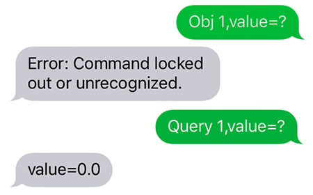
You can query the present value of a data object using "obj 1,value=?". However, if the i.Report is password protected and the session is locked, you will get an error message (assuming your phone number is found in the phonebook, ignored completely if not).
Users found in the phonebook but whose session is locked will not be allowed to use the "obj" command because that is considered a configuration command. If their session is unlocked but they are not authorized for issuing commands, they will still get the error message.
Users not authorized for commands can use the "query" command instead. Users must be found in the phonebook before they will get any response. But as long as the user is known, they can use the query command to check on values.
Most of the "show" commands can also be used by known users even if not authorized for other commands used to make changes.
The link LED labeled LNK on the cover of the VP3-TM is connected directly to the cellular modem. The possible indications of the LNK LED are as follows:
| LNK LED is: | What it means: |
| OFF | Possible hardware failure if LED remains in this state. |
| ON | Not connected to network, but trying. |
| Flash @ 2/Sec | Connected to network, operating normally. |
| Flash twice, pause, repeat | Connected to network, operating, but last attempt to send a message failed. |
While connected to the VP3-TM in configuration mode, you can use the "show cell" command to check signal strength. If connected to the network, you will see a "Signal: xx dBm" indication. Signal strength will be indicated as a number in the range of -51 dBm to -113 dBm with -51 being a perfect signal and -113 being call-dropping bad.
You can also use the "show cell" command remotely via SMS. Of course if the signal is too weak to send a message, you are not going to get a reply, and therefore the "show cell" remotely is merely a confirmation of signal strength. It can still have some value remotely. If you are getting messages intermittently and see a signal strength closer to the bottom end of the range, this may be a useful clue as to why messages are intermittent.
The VP3-TM attempts to be as helpful as possible in detecting and reporting communication faults while in operation. These will be reported via SMS, but only to those users who have been selected to receive them. Enable error and failure messages per user in the Users configuration (Section 9).
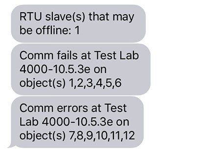
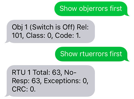
The automatic notification of communication faults will indicate which objects are having problems. From there, you need to do further queries to see exactly what the nature of the problem is.
All models of VP3-TM provide a fault code denoted as "Rel" for reliability, and also provide an error class and error code. Some models provide additional queries relevant at the device level. The entire list of queries available is outlined in Section 11.
Each object has three possible error indicator fields: Reliability, Error Class, Error Code, as defined by BACnet protocol. The Modbus version of the device uses these same error fields for consistency, but ultimately only the reliability value, which Modbus will refer to as “fault code”, will be returned via Modbus virtual objects.
Modbus error class and codes are arbitrarily assigned, and do overlap BACnet codes. One needs to simply look at the codes relevant to the protocol in use to determine their meaning. The reliability codes that is derived from the class and code are uniquely Modbus or BACnet, and as BACnet reliability codes, do conform to BACnet protocol boundaries.
Modbus error class/codes:
Class 0, code 1 = no response
Class 0, code 2 = CRC error
Class 1, code N = exception code N
code 1 = illegal function code
code 2 = illegal data address
code 3 = illegal data value
code 10 = gateway path unavailable (TCP gateway not responding)
(see Modbus spec for additional uncommon exceptions)
Class 2, code 2 = faulty Modbus packet
Class 2, code 4 = configuration fault
Modbus reliability code will be (((class+1) * 100) + code).
Modbus fault (reliability) codes:
101 = no response
102 = CRC error
201 = Modbus exception, illegal function code
202 = Modbus exception, illegal data address
203 = Modbus exception, illegal data value
210 = Modbus exception, gateway path unavailable
2XX = Modbus exception, other where XX is exception code, see Modbus spec
302 = Faulty Modbus packet
304 = Configuration fault
Each object has three possible error indicator fields: Reliability, Error Class, Error Code, as defined by BACnet protocol. Since the VP3-BTM is not a gateway, its protocol usage is mutually exclusive and will be either Modbus or BACnet but never both.
The error class and code will be retained upon receipt by the BACnet client, but these codes will result in a single reliability code that is derived from class and code. Since we assume repeated attempts will return the same error code and class, the code/class will be retained immediately but transitioning of reliability code from zero to non-zero can be delayed by the default count set by “defaultonfails”.
BACnet reliability code will be (((class+1)*1000) + code) where class may be 0..3, and any class above 3 capped at class 4.
Example: A common error is trying to read an object in another device that does not exist in that device. The device will return error class 1, code 31. This will become fault/reliability code 2031 as reported via SMS. If the remote device is not responding, this will internally generate class 0, code 300, reported as fault/reliability code 1300 via SMS. As an SMS message, this code will be called “fault”. If queried as a BACnet object property, it will be returned as the reliability value.
Proprietary error codes:
300 = Response timeout
301 = Configuration error
302 = BACnet error code “other” was received from remote device
303 = Unable to allocate invoke ID
All other error classes/codes are per BACnet standard, copied here from the open source BACnet project bacenum.h file (the BACnet standard itself cannot be copied).
0 = ERROR_CLASS_DEVICE
1 = ERROR_CLASS_OBJECT
2 = ERROR_CLASS_PROPERTY
3 = ERROR_CLASS_RESOURCES
4 = ERROR_CLASS_SECURITY
5 = ERROR_CLASS_SERVICES
/* valid for all classes */
0 = ERROR_CODE_OTHER
/* Error Class - Device */
2 = ERROR_CODE_CONFIGURATION_IN_PROGRESS
3 = ERROR_CODE_DEVICE_BUSY
25 = ERROR_CODE_OPERATIONAL_PROBLEM
/* Error Class - Object */
4 = ERROR_CODE_DYNAMIC_CREATION_NOT_SUPPORTED
17 = ERROR_CODE_NO_OBJECTS_OF_SPECIFIED_TYPE
23 = ERROR_CODE_OBJECT_DELETION_NOT_PERMITTED
24 = ERROR_CODE_OBJECT_IDENTIFIER_ALREADY_EXISTS
27 = ERROR_CODE_READ_ACCESS_DENIED
31 = ERROR_CODE_UNKNOWN_OBJECT
36 = ERROR_CODE_UNSUPPORTED_OBJECT_TYPE
/* Error Class - Property */
8 = ERROR_CODE_INCONSISTENT_SELECTION_CRITERION
9 = ERROR_CODE_INVALID_DATA_TYPE
32 = ERROR_CODE_UNKNOWN_PROPERTY
37 = ERROR_CODE_VALUE_OUT_OF_RANGE
40 = ERROR_CODE_WRITE_ACCESS_DENIED
41 = ERROR_CODE_CHARACTER_SET_NOT_SUPPORTED
42 = ERROR_CODE_INVALID_ARRAY_INDEX
44 = ERROR_CODE_NOT_COV_PROPERTY
45 = ERROR_CODE_OPTIONAL_FUNCTIONALITY_NOT_SUPPORTED
47 = ERROR_CODE_DATATYPE_NOT_SUPPORTED
50 = ERROR_CODE_PROPERTY_IS_NOT_AN_ARRAY
/* Error Class - Resources */
18 = ERROR_CODE_NO_SPACE_FOR_OBJECT
19 = ERROR_CODE_NO_SPACE_TO_ADD_LIST_ELEMENT
20 = ERROR_CODE_NO_SPACE_TO_WRITE_PROPERTY
/* Error Class - Security */
1 = ERROR_CODE_AUTHENTICATION_FAILED
6 = ERROR_CODE_INCOMPATIBLE_SECURITY_LEVELS
12 = ERROR_CODE_INVALID_OPERATOR_NAME
15 = ERROR_CODE_KEY_GENERATION_ERROR
26 = ERROR_CODE_PASSWORD_FAILURE
28 = ERROR_CODE_SECURITY_NOT_SUPPORTED
30 = ERROR_CODE_TIMEOUT
/* Error Class - Services */
5 = ERROR_CODE_FILE_ACCESS_DENIED
7 = ERROR_CODE_INCONSISTENT_PARAMETERS
10 = ERROR_CODE_INVALID_FILE_ACCESS_METHOD
11 = ERROR_CODE_ERROR_CODE_INVALID_FILE_START_POSITION
13 = ERROR_CODE_INVALID_PARAMETER_DATA_TYPE
14 = ERROR_CODE_INVALID_TIME_STAMP
16 = ERROR_CODE_MISSING_REQUIRED_PARAMETER
22 = ERROR_CODE_PROPERTY_IS_NOT_A_LIST
29 = ERROR_CODE_SERVICE_REQUEST_DENIED
43 = ERROR_CODE_COV_SUBSCRIPTION_FAILED
46 = ERROR_CODE_INVALID_CONFIGURATION_DATA
48 = ERROR_CODE_DUPLICATE_NAME
49 = ERROR_CODE_DUPLICATE_OBJECT_ID

Any time the VP3-TM restarts, a restart message will be sent to any users in groups that have been selected to receive them by checking "Starts" on the Groups configuration page. The site name and restart code will be included in the message. The restart code will be indicated as "[a/b]" where the "a" and "b" are numbers identified below.
The restart code [1/0] is simply a power-up cold start. This code is normal. If you use the "sys reboot=all" command to remotely restart the VP3-TM, the restart code will be [5/0] and would also be considered normal in this case. Any other combination of numbers would indicate something unexpected, for which you should seek technical support.
Restart reason "a":
1 = cold start/power-up
2 = restart due to application fault code (or BACnet warm start)
5 = restart due to processor fault code
6 = watchdog timeout
Fault code "b" if nonzero:
Codes 1-5 are low level processor aborts (restart reason 5):
0 = requested restart, no fault
1 = undefined instruction
2 = program abort (instruction address fault)
3 = data abort (memory address fault)
4 = uncaught interrupt (IRQ)
5 = uncaught fast interrupt (FIRQ)
6 = stack overflow
Codes 7-12 are application level system errors (restart reason 2):
7 = system configuration CRC error
8 = bad parameter in system configuration
9 = EEPROM read failure
10 = EEPROM write failure
11 = EEPROM lock failure
12 = object allocation failure
Codes 20-25 are application requested restarts from the crash monitor (restart reason 2):
20 = modem handler unresponsive
21 = excessive modem restarts
22 = data scanner unresponsive
23 = communication client unresponsive
24 = communication engine unresponsive
25 = main program unresponsive
Depending on the error condition present, it is possible that the error will go unreported due to the system's inability to send a text message. In the event any of the above codes do show up, these are their meanings.
SMS failure to send will be captured and reported as a user error that may be viewed with the "show usererrors" command. The VP3-TM will not attempt to send a message if there is no network connection, but the "no network registration" error could occur if the connection dropped right in the middle of processing the message. Otherwise, the only failure that is likely to occur is trying to send to an invalid mobile number.
0x00 = SMS successfully sent.
0x01 = SMS failed to send.
0x02 = Invalid SMS parameters - check P# (Destination Phone Number).
0x03 = SMS not supported.
0x10 = No network registration.
0x11 = Cellular component stack error.
0x13 = Socket leak
0xFF = No SMS state to report (no SMS messages have been sent).
Copyright © 2019 Control Solutions Minnesota, Inc.