
The link LED labeled LNK on the cover of the VP3-TM is connected directly to the cellular modem. The possible indications of the LNK LED are as follows:
| LNK LED is: | What it means: |
| OFF | Possible hardware failure if LED remains in this state. |
| ON | Not connected to network, but trying. |
| Flash @ 2/Sec | Connected to network, operating normally. |
| Flash twice, pause, repeat | Connected to network, operating, but last attempt to send a message failed. |
The fact that you are in configuration mode will be indicated by the LED labeled “STA” remaining on solid amber. In normal operation, this LED will be off, or flashing. If on solid amber, you are in configuration mode.
| STA LED is: | What it means: |
| ON | You are in configuration mode. |
| OFF or Flashing | You are not in configuration mode. When not in configuration mode, the meaning of the STA LED will vary by model, as outlined in following sections. |
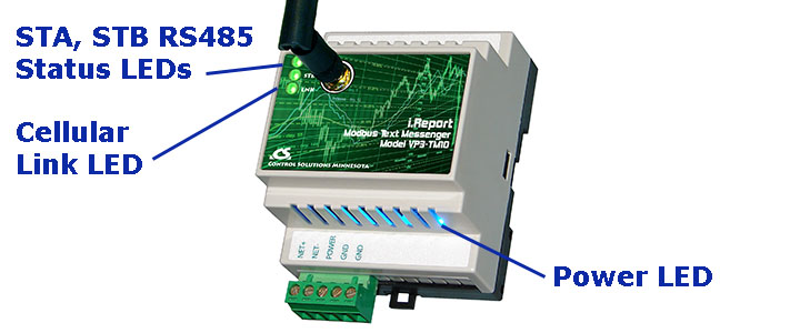
Power-up LED behavior: STA and STB LEDs on front panel will turn on yellow or red for half a second, then all will turn on green for half a second. Then they will proceed to indicate as normally defined for the indicators. The power LED will be lighted (blue) any time power is applied to the unit.
The STA and STB LED indicators on the front of the VP3-TM10 indicate Modbus errors. These are global indicators that do not tell you which device or which register is having trouble, but these indicators are a very quick way to observe whether there are problems, and also whether there is any activity at all.
The STA and STB LEDs will indicate Modbus traffic as indicated in the table below.
| Mode | "STA" LED | "STB" LED |
| VP3-TM10 is Master | Flash yellow each time master (VP3-TM10) sends a request to a remote slave. | Flash green when master receives a good response.
Flash red when master receives exception message from slave, or if timed out with no response from slave. |
| VP3-TM10 is Slave | Flash yellow each time slave (VP3-TM10) receives a request from external master. | Flash green when slave recognizes request as good/valid and sends a good reply.
Flash red when slave receives a request that results in replying with an exception, or there was a CRC error in the request. |

Power-up LED behavior: STA and STB LEDs on front panel will turn on yellow or red for half a second, then all will turn on green for half a second. Then they will proceed to indicate as normally defined for the indicators. The power LED will be lighted (blue) any time power is applied to the unit.
The LEDs will indicate BACnet traffic as indicated in the table below.
| Mode | "STA" LED | "STB" LED |
| VP3-TM30 is Client or Server |
"Token" LED Flash yellow each time the VP3-TM30 sends a "poll for master". Flash green each time the token is passed. |
"Packet" LED Flash green any time a packet is sent on the network. This can be either a request or a response to a request Flash red any time an error is detected. The error can be an error code reply, or timeout. The object reliability code will indicate which one it was. |

Power-up LED behavior: STA and STB LEDs on front panel will turn on yellow or red for half a second, then all will turn on green for half a second. The STC and STD LEDs will replicated this behavior but after a delay. Then they will proceed to indicate as normally defined for the indicators. The power LED will be lighted (blue) any time power is applied to the unit.
The STC and STD LEDs will indicate Modbus traffic as indicated in the table below.
| Mode | "STC" LED | "STD" LED |
| VP3-TM60 is Master | Flash yellow each time master/client (VP3-TM60) sends a request to a remote slave/server.
If TCP is unable to make a connection with the IP address given for the TCP slave, the request LED will not flash yellow (because no request was sent yet), but the reply LED will flash red each time the connection attempt times out or fails. |
Flash green when master receives a good response.
Flash red when master receives exception message from slave, or if timed out with no response from slave. |
| VP3-TM60 is Slave | Flash yellow each time slave (VP3-TM60) receives a request from external master. | Flash green when slave recognizes request as good/valid and sends a good reply.
Flash red when slave receives a request that results in replying with an exception. |
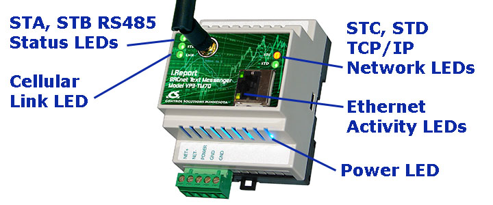
The Ethernet activity LEDs include a green traffic LED and yellow link LED integrated into the CAT5 connector.
The Ethernet traffic LED will indicate any traffic on the Ethernet network, and does not necessarily indicate TCP traffic. The traffic LED will typically be off more than on, flashing on each time traffic is indicated. If the traffic LED is on completely solid, the server is not running (normal for a half minute or so during startup).
The Ethernet link LED will be on any time there is a connection to the network. If the Ethernet cable is unplugged, this light will go out. If Modbus TCP is failing and this light is out, check Ethernet cables.
Power-up LED behavior: STA and STB LEDs on front panel will turn on yellow or red for half a second, then all will turn on green for half a second. The STC and STD LEDs will replicate this behavior but after a delay. Then they will proceed to indicate as normally defined for the indicators. The power LED will be lighted (blue) any time power is applied to the unit.
The STC and STD LEDs will indicate BACnet traffic as indicated in the tables below.
| Mode | "STC" LED | "STD" LED |
| VP3-TM70 is Client (Master) |
Flash yellow each time VP3-TM70 sends a request to a remote server (slave). | Flash green when VP3-TM70 receives a good response.
Flash red when VP3-TM70 receives error code message from server, or if timed out with no response from server. |
| VP3-TM70 is Server (Slave) |
Flash yellow each time VP3-TM70 receives a request from external client. | Flash green when VP3-TM70 recognizes request as good/valid and sends a good reply.
Flash red when VP3-TM70 receives a request that results in replying with an error code. |
The Ethernet activity LEDs include a green traffic LED and yellow link LED integrated into the CAT5 connector.
The Ethernet traffic LED will indicate any traffic on the Ethernet network, and does not necessarily indicate BACnet IP traffic. The traffic LED will typically be off more than on, flashing on each time traffic is indicated. If the traffic LED is on completely solid, the server is not running (normal for a half minute or so during startup).
The Ethernet link LED will be on any time there is a connection to the network. If the Ethernet cable is unplugged, this light will go out. If BACnet IP is failing and this light is out, check Ethernet cables.
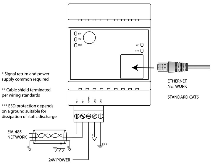
Wire the VP3-TMxx as illustrated above. Follow all conventional standards for wiring of EIA-485 networks when connecting the EIA-485 (RS485) network. This includes use and termination of shield, termination of the network, and grounding.
IMPORTANT: Although EIA-485 (RS485) is thought of as a 2-wire network, you MUST include a third conductor connected to GND or common at each device so that all devices are operating at close to the same ground potential. Proper grounding of equipment should ensure proper operation without the third conductor; however, proper grounding often cannot be relied upon. If large common mode voltages are present, you may even need to insert optically isolated repeaters between EIA-485 devices.
Use standard CAT5 cables for Ethernet connections. Use control wire as applicable for local electrical codes for connecting the 24V (AC or DC) power supply. (Denoted as most commonly used 24V here, can vary per specification.)
Note that in addition to connecting power supply common to a GND terminal, you must also connect a GND terminal to earth ground in order to ensure proper ESD protection.
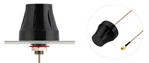
Antenna Connection
The stanard antenna connected to the front of the VP3-TMxx will be suitable for many applications. However, if the VP3-TMxx is placed inside a metal control panel, for example, the cellular signal may be degraded if not outright blocked. In this case, it is suggested that an RF cable with SMA connectors be used to extend the reach of the antenna to outside of the control panel. Additional antenna options are available for remote mounting. Contact Control Solutions technical support.
ESD Protective Measures
WARNING: Opening any electronic device for any reason including positioning of jumpers can cause damage or destruction of the device if proper ESD handling procedures are not followed!
WARNING: Always remove power from device before opening it! This is for the protection of the device. You will not be harmed by the low voltage present, but you may cause damage or destruction of the device by opening it with power connected.
Recommended Procedure
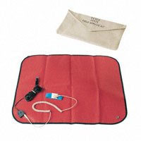
You should be working at an ESD safe workstation that includes grounded static mat and grounded wrist strap, and you should be wearing the wrist strap connected to the grounded static mat while opening and working with the opened device. For field service purposes, a portable static mat and wrist strap are available at this link: http://www.digikey.com/product-detail/en/16475/16-1235-ND
Emergency Backup Plan:
Follow this practice if you do not have proper ESD equipment on hand but must open the device anyway. Find something that is a solid ground like metal water pipe or grounded metal electrical conduit. Touch ground to discharge static on your body before touching the internal parts of the device. Ideally you should connect a ground wire to the GND terminal of the device and make simultaneous contact between the GND terminal, yourself, and the source of earth ground. Make certain no power is connected to the device while grounding it, opening it, or working with it. If you set the device down, be sure to repeat the discharge of static on your body before touching the device again.
WARNING: The LED indicators on the daughter cards are fragile. Do not handle by edges such that you come in contact with the LEDs. They will potentially break off the board.
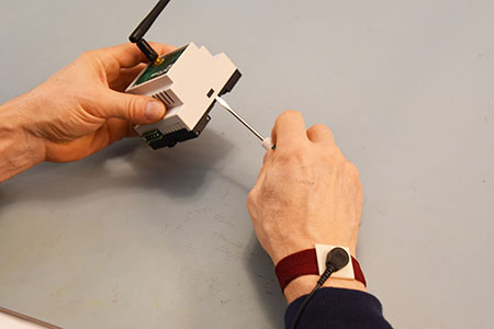
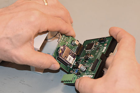
Use a very small screw driver to slide the cover up and over the black tabs located one on each side of the VP3-TMxx.
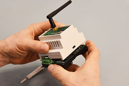
Carefully lift the cover straight up and away from the base. Be careful to not exert side-way force on the daughter card. DO NOT try to move the cover more than 4 inches away from the base. Avoid touching the LEDs.
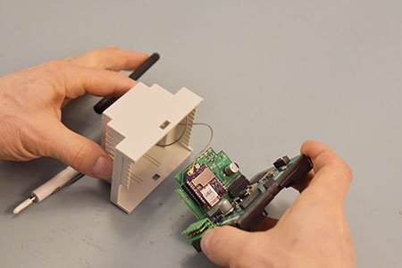
The antenna is attached internally to the modem on the daughter card with a delicate RF cable. DO NOT disconnect this cable. The UFL connector on the modem is not designed for repeated removal and reattachment.
Carefully reverse this procedure when closing the device.
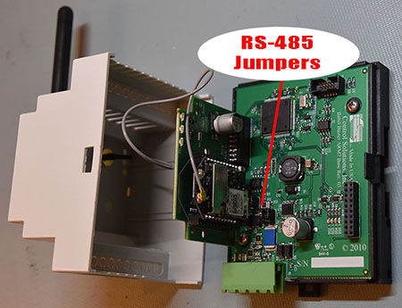
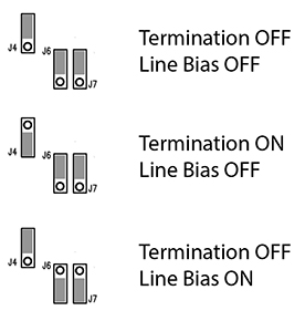
Enable line termination only when this device is placed at the end of the network. Termination should only be enabled at two points on the network, and these two points must be specifically the end points.
Enable line bias when needed. Line bias should only be enabled at one point on the network, and does not have to be the end point. Line bias holds the line in a known neutral state when no devices are transmitting. Without bias, the transition from offline to online by a transmitter can look like a false start bit and cause loss of communication.
The line conditioning options are enabled when the respective shunt is moved to the position indicated in the drawing above.
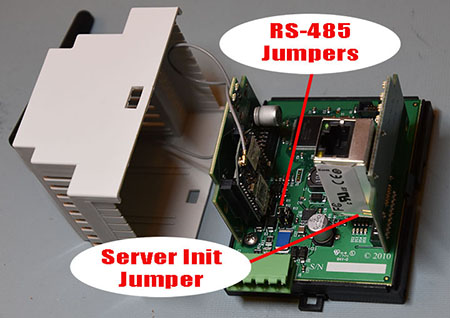
The "Init" jumper on the server module should only be used when advised by tech support. Installing this jumper prior to power-up causes the server to go into firmware update mode.
Refer first to Appendix section F.7 regarding proper handling and opening the VP3-TMxx device.
It is necessary to unplug the daughter card from the main board in order to remove or insert the SIM card. Be sure you are following ESD precautions noted above when doing this. The daughter card format has been used successfully for multiple wireless technologies. Unfortunately, when adopting this same format for cellular, the location of the SIM card slot suffered. Because the SIM card is difficult to access, it is preferred that VP3-TMxx devices be shipped with the SIM card pre-installed.
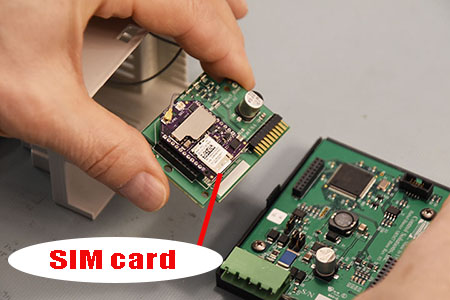
The SIM card slot is located at the bottom of the daughter card.
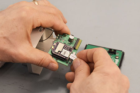
Gently push in on the SIM card to unlatch it and remove it. It has a toggling latching mechanism. You will feel a "click" when pushing the card in to remove or to insert. The electrical contacts on the SIM card should face down (toward circuit board) and the beveled corner of the card should be toward the outside.
Be very careful when returning the daughter card to its position on the main board. See that the pins are aligned correctly. Failure to do so will result in hardware failure. Do not force pin insertion. The connector will slide in easily if aligned correctly.
Copyright © 2019 Control Solutions Minnesota, Inc.